40 | ni.com | NI Digital System Development Board User Manual
Seven-Segment Display
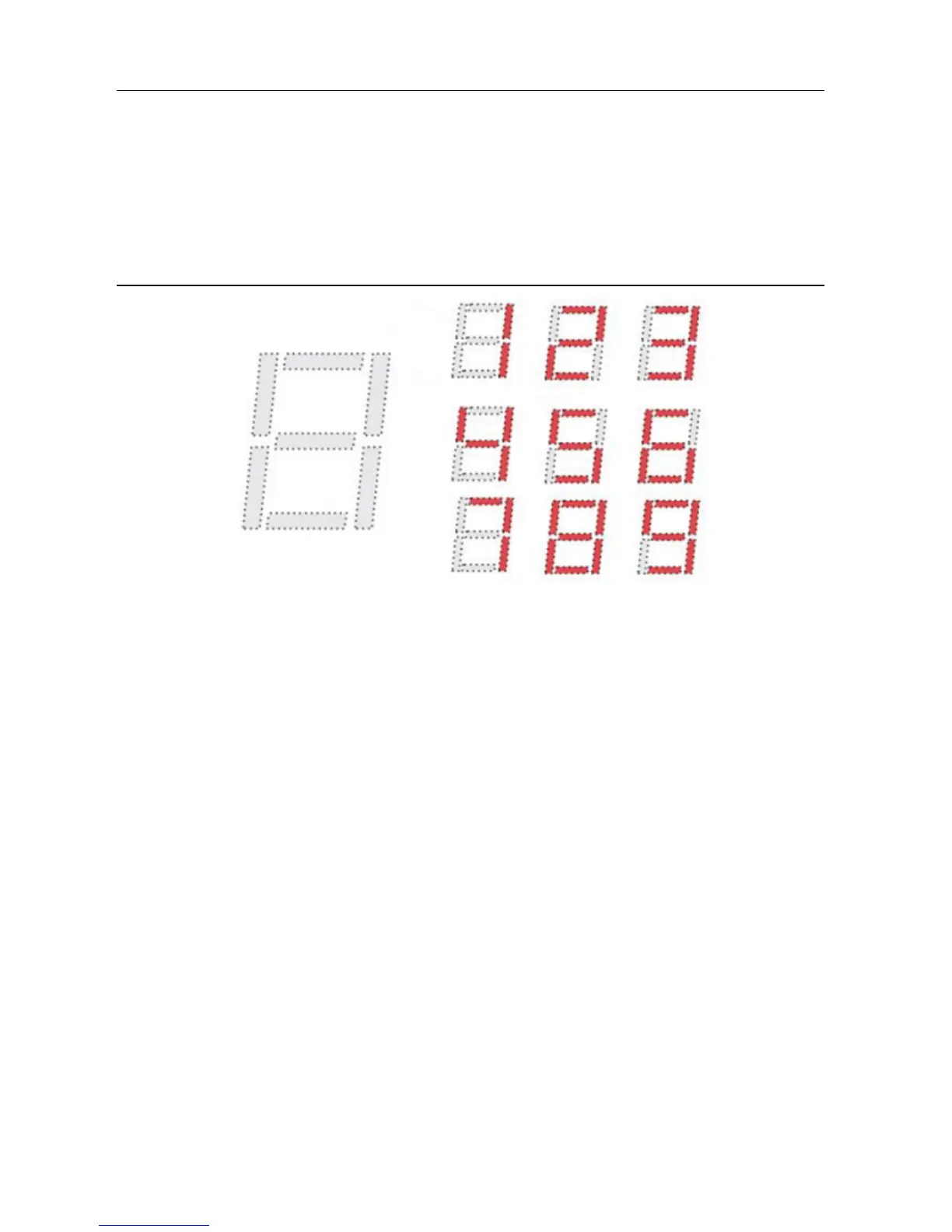
The DSDB contains a four-digit common anode seven-segment LED display. Each of the four
digits is composed of seven segments arranged in a “figure 8” pattern, with an LED embedded
in each segment. Segment LEDs can be individually illuminated, so any one of 128 patterns can
be displayed on a digit by illuminating certain LED segments and leaving the others dark, as
shown in Figure 16. Of these 128 possible patterns, the ten corresponding to the decimal digits
are the most useful.
Figure 16. Digit Illumination Patterns
The anodes of the seven LEDs forming each digit are tied together into one common anode
circuit node, but the LED cathodes remain separate, as shown in Figure 17. The common anode
signals are available as four digit enable input signals to the 4-digit display. The cathodes of
similar segments on all four displays are connected into seven circuit nodes labeled CA through
CG. For example, the four D cathodes from the four digits are grouped together into a single
circuit node called CD. These seven cathode signals are available as inputs to the 4-digit display.
This signal connection scheme creates a multiplexed display, where the cathode signals are
common to all digits but they can only illuminate the segments of the digit whose corresponding
anode signal is asserted.
To illuminate a segment, the anode should be driven high while the cathode is driven low.
However, since the DSDB uses transistors to drive enough current into the common anode point,
the anode enables are inverted. Therefore, both the AN0..3 and the CA..G/DP signals are driven
low when active.
 Loading...