NI Digital System Development Board User Manual | © National Instruments | 45
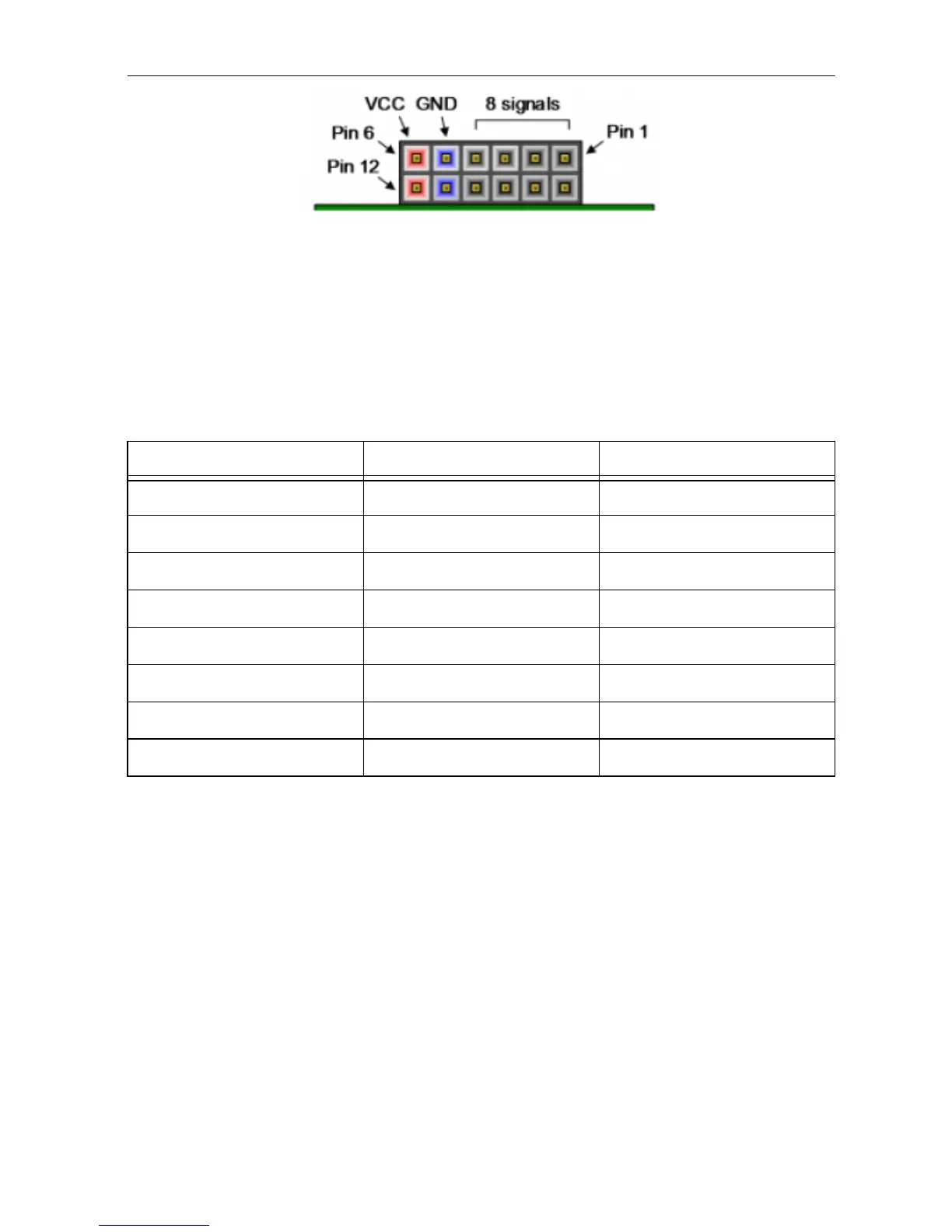
Figure 20. Pmod Connector, front view
Digilent produces a large collection of Pmod accessory boards that can attach to the Pmod
expansion connectors to add ready-made functions like A/D’s, D/A’s, motor drivers, sensors, and
other functions. Visit www.digilentinc.com for more information on Pmods.
The DSDB has three Pmod connectors, some of which behave differently than others. Each
Pmod connector falls into one of two categories: standard or MIO connected. Table 26 specifies
which category each Pmod falls into, and also lists the Zynq pins they are connected to.
The following sections describe the differences between the Pmod types.
Standard Pmod
The standard Pmod connectors are connected to the PL of the Zynq via the protection circuit
described in section User IO Protection, which limits the minimum pulse-width to 20 ns
(50 MHz).
MIO Pmod
The MIO Pmod connector is connected to the MIO but in the PS of the Zynq via protection
circuitry. Like the standard Pmod connector, this circuit adds protection at the cost of maximum
switching speed. Since these data signals are connected to the MIO interface, they can only be
accessed by the PS peripheral controller cores. The GPIO, UART, I2C, and SPI cores can all be
used to drive devices connected to this Pmod. Note that the pin layout of the UART and I2C
Table 26. Pmod Pinout
Pmod JA (Standard) Pmod JB (Standard) Pmod JC (MIO)
JA1: AA11 JB1: AB6 JC1: A6
JA2: AA12 JB2: AB7 JC2: B4
JA3: AB10 JB3: AB4 JC3: C5
JA4: AA9 JB4: AB2 JC4: G7
JA7: AB11 JB7: AA6 JC7: B6
JA8: AB12 JB8: AA7 JC8: C4
JA9: AB9 JB9: AB5 JC9: G6
JA10: AA8 JB10: AA4 JC10: E6
 Loading...