NI Digital System Development Board User Manual | © National Instruments | 37
The addressing mode of the I2C is 7 bit, with the slave address being 0111000 in binary and the
maximum frequency at which the controller can operate is 400 KHz. In addition to the I2C bus,
there are two other signals provided by the controller; the RESET and the INT signal. In order
to reset the touch panel controller, the RESET pin has to be driven low for at least 1 ms. The INT
signal is an I/O signal which will go low while the panel is being touched. Also, when the
FT5x16 is in hibernation, the same INT signal must be used in order to wake the controller up.
When using the INT signal in order to wake the controller, the low pulse generate for the
wake-up sequence must be driven low for 0.5 to 1 ms. The reason for this short period is that the
INT port will act as an interrupt output port after the wake-up.
The following registers can be used in order to obtain a minimal functionality of the touch panel:
This is the device mode register, which is configured to determine the current mode of the
chip.(Read/Write)
This register describes MSB of the X coordinate of the nth touch point and the corresponding
event flag.(Read only)
Table 18. Touch Panel Pinout
Pin Signal Description
1 VCC 3.3 V
2 TP_SCK I2C clock signal
3 TP_SDA I2C data signal
4 TP_IRQ Interrupt/wake-up signal
5 TP_RES Reset signal, has a pull-up resistor
6 GND Ground
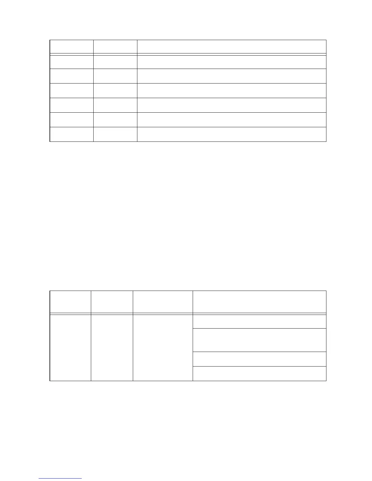
Table 19. Device Mode Register
Address
Bit
Address
Register Name Description
00h 6:4 Device Mode
[2:0]
000b Normal operating Mode
001b System Information Mode
(Reserved)
100b FACTORY MODE0 (Reserved)
110b FACTORY MODE1 (Reserved)
 Loading...