12
ASSEMBLY
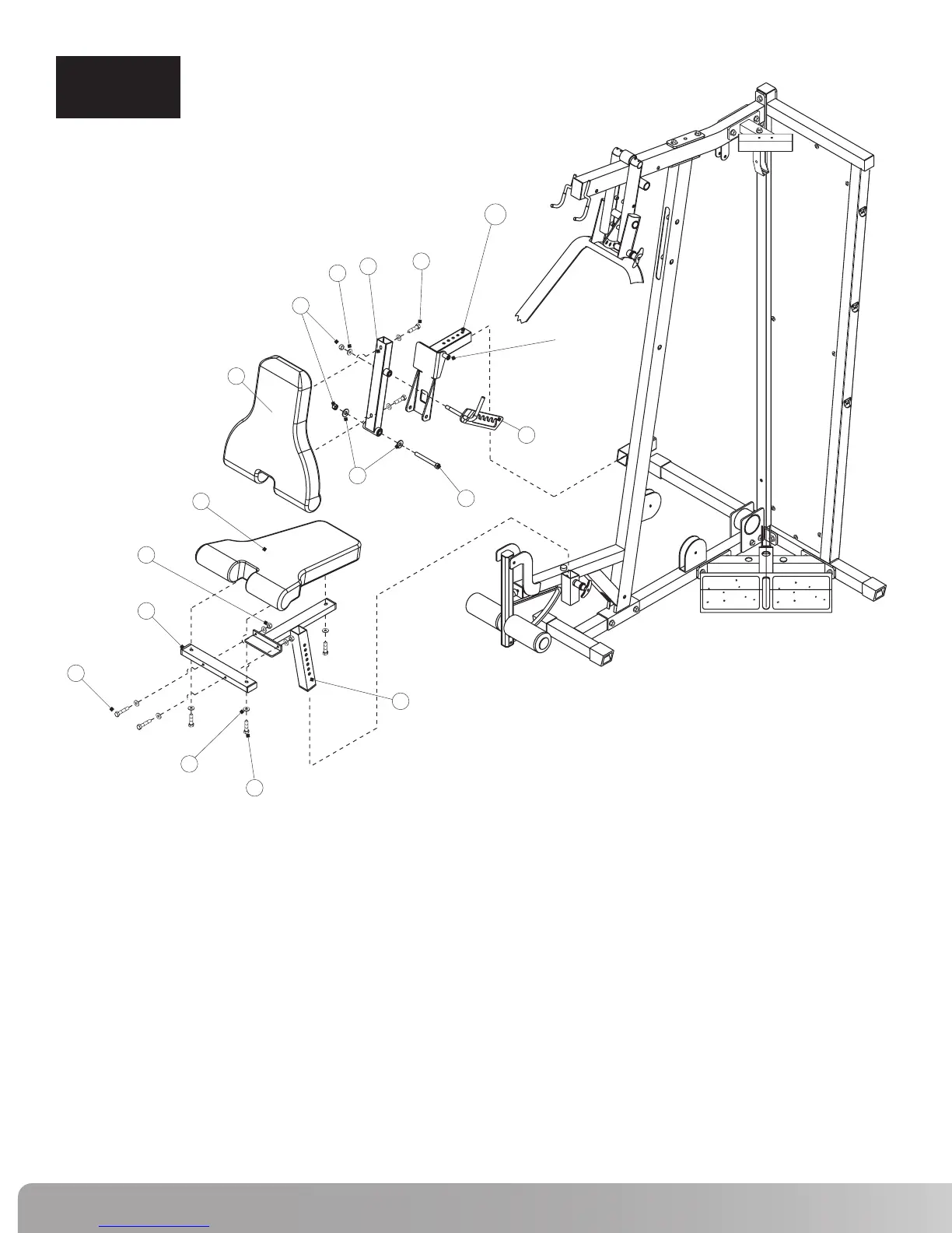
STEP 4
# Component Qty
Step 4 Components:
Procedure:
A. Attach Seat Cross Tube (28) to Seat Adjuster (27) using hardware shown.
Tighten hardware securely.
B. Attach Seat Pad (31) to Seat Cross Tube (28) and Seat Adjuster (27) using
hardware shown. Tighten hardware securely.
C.
Install Seat adjuster (27) in Front Upright Frame in the slot shown.
Use Pop Pin to adjust seat height.
Note: Pop Pin is threaded so that seat can be locked in position.
D. Attach Back Pad Tube (29) to Back Pad (32) using hardware shown.
Tighten hardware securely.
E.
Attach Back Pad Tube (29) to Back Pad Adjuster (29a) using hardware shown.
Tighten hardware securely but still allowing Back Pad Tube to rotate freely.
F.
Install Back Pad Adjuster (29a) in Front Upright Frame in the slot shown. Use the
Pop Pin to adjust the Back Pad location.
NOTE: Pop Pin is threaded so that the seat can be locked in position.
G. Attach Back Pad Adjustment (30) to Back Pad Tube (29) using hardware
shown making sure that the Back Pad Adjustment Pin rests inside the slot
of the Back Pad Adjustment. Tighten hardware securely but still allowing
Back Pad Adjustment to rotate freely.
27
28
29
29a
30
31
32
46
50
53
55
58
59
60
61
Seat Adjuster
Seat Cross Tube
Back Pad Tube
Back Pad Adjuster
Back Pad Adjustment
Seat Pad
Back Pad
Hex Bolt 1/2” x 4 1/2”L
Hex Bolt 3/8” x 3”L
Hex Bolt 3/8” x 2 1/4”L
Hex Bolt 3/8” x 1 3/4”L
1/2” Flat Washer
3/8” Flat Washer
1/2” Lock Nut
3/8” Lock Nut
1
1
1
1
1
1
1
1
2
2
3
3
9
2
2
50
59
55
27
28
61
31
32
58
46
29
29a
58
60
53
30
41/2”L
2 1/4”L
3”L
1 3/4”L
BACK PAD
ADJUSTMENT
PIN
 Loading...