15
Nautilus NS200X
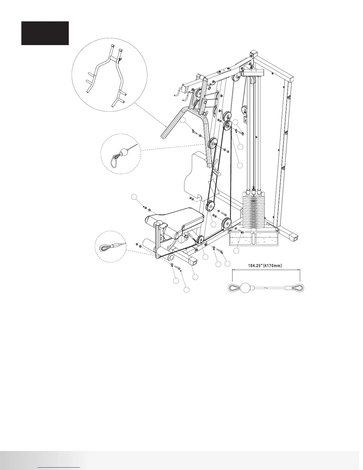
Step 7 Components:
Procedure:
ASSEMBLY
STEP 7
# Component Qty
A. Draw Cable #3 (43) over a 4 ½” Pulley (13) and place Pulley in middle slot of
Front Upright Frame. Attach using hardware shown. Tighten hardware
securely. Note cable termination in Detail A.
B. Loop Cable #3 (43) around a 4 ½” Pulley (13) and attach Pulley to the low
bracket on the Front Upright Frame using the hardware shown. Tighten
hardware securely.
C. Loop Cable #3 (43) around a 4 ½” Pulley (13) and place in the Double
Floating Pulley Bracket shown. Attach Pulley to inner hole using hardware
shown. Tighten hardware securely.
D. Draw Cable #3 (43) around a 4 ½” Pulley (13) and attach Pulley to the
bracket on the Main Base Frame using hardware shown. Tighten hardware
securely.
E. Draw Cable #3 (43) under a 3 ½” Pulley (14) and attach Pulley to the Front
Upright Frame in the low slot using hardware shown. Tighten hardware
securely.
F. Attach Cable #3 (43) termination shown in Detail B to the Leg Extension
Assembly using hardware shown. DO NOT OVER TIGHTEN.
13
14
43
51
52
54
59
61
63
64
4 ½” Pulley
3 ½” Pulley
Cable #3 - Leg Extension (164.25”)
Hex Bolt 3/8” x 2 3/4”L
Hex Bolt 3/8” x 2 1/2”L
Hex Bolt 3/8” x 2”L
3/8” Flat Washer
3/8” Lock Nut
Step Spacer - 5/8”H
Step Spacer - 7/8”H
4
1
1
2
1
3
6
6
4
2
61
51
14
64
63
59
40
54
51
13
43
52
54
2”L
2”L
2 3/4”L
2 3/4”L
2 ½ ”L
A
B
NS200X Press Arm
 Loading...