8 |
About your AIS/VHF antenna splitter | NSPL-400 User Manual
end (for connection to the NSPL-400) and a PL259 connection at the
opposite end (for connection to the AIS transceiver).
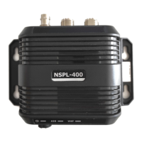
• NSPL-400 AIS/VHF antenna splitter unit
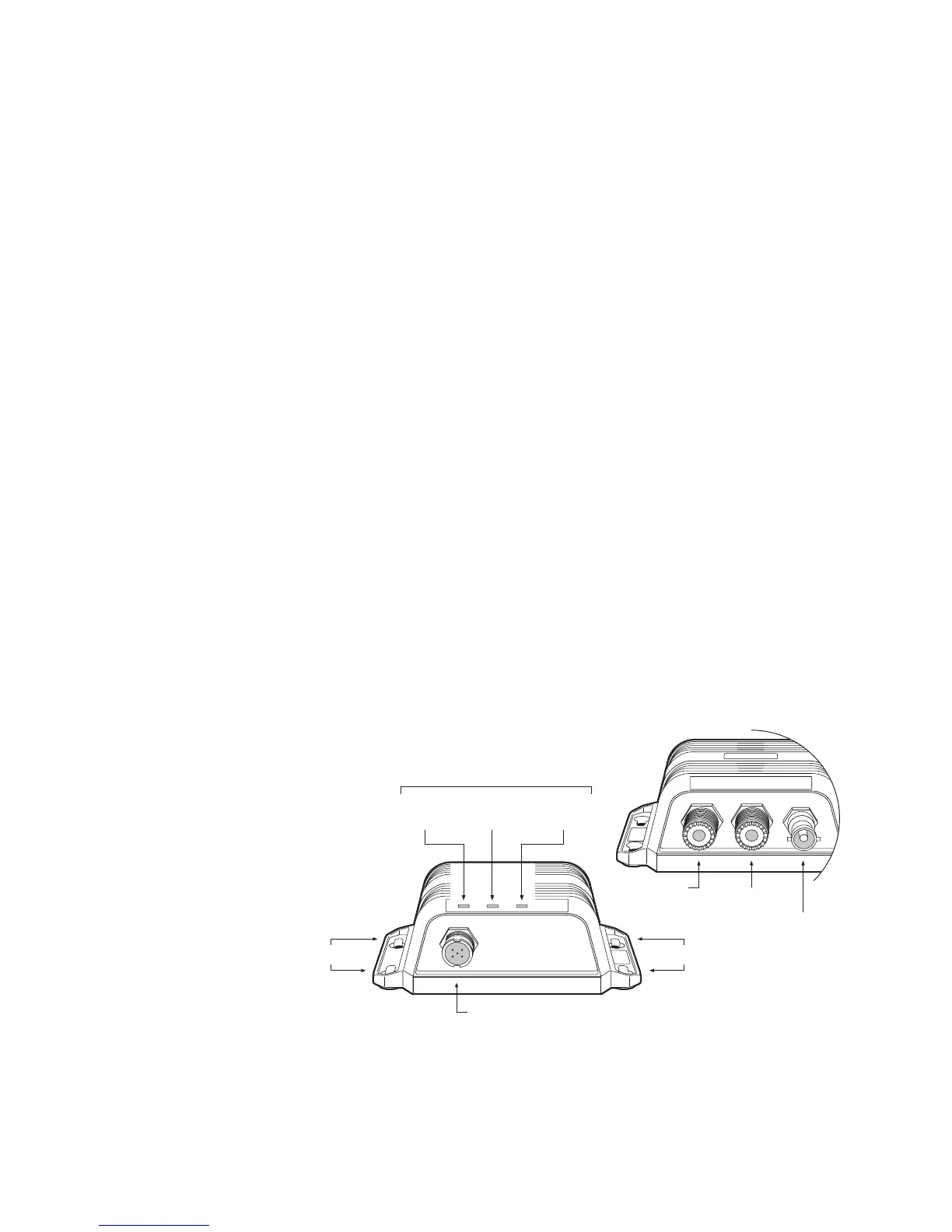
Figure 2 shows an overview of the NSPL-400 unit.
The NSPL-400 has a number of indicators which provide information
to the user about the status of the NSPL-400. Please refer to section
4 for more details of the indicator functions.
The NSPL-400 mounting holes are located as shown in Figure 2.
Please refer to the Installation procedure section for details of how
to mount the NSPL-400.
• Power and FM cable
The power and FM cable connects to the NSPL-400 and enables
connection to power and an FM radio antenna input.
Electrical connections
The NSPL-400 has the following electrical connections as shown in
Figure 2.
• Power supply
• VHF antenna connector
• VHF radio connector
• AIS transceiver connector
• FM radio connector
Mounting holesMounting holes
VHF antenna
VHF radio
Power and FM Radio
AIS transceiver
Indicator lights
Green Yellow Yellow
(Power) (AIS TX) (VHF TX)
AIS transceiver
VHF radio
VHF antenna
Power and FM Radio
Mounting holes
Green Yellow Yellow
Mounting holes
(Power) (AIS TX) (VHF TX)
Indicator lights
Figure 2 AIS/VHF antenna splitter overview
 Loading...