| 15
Installation | NSPL-400 User Manual
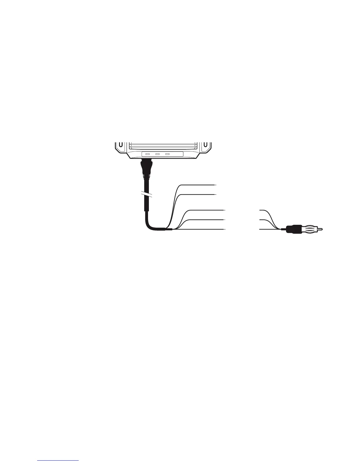
Step 5 - Connecting the power supply and optional FM output
The NSPL-400 requires a 12 V or 24 V power supply typically pro-
vided by the vessel’s battery. It is recommended that crimped
and soldered lugs are used to connect the NSPL-400 to the power
source. It is recommended that the power supply is connected via a
suitable circuit breaker and/or 1A fuse block.
1. Connect the red wire to the power supply positive terminal.
2. Connect the black wire to the supply negative terminal.
3. Connect the FM connector to the FM radio antenna input.
Power in +
Power in –
FM output
FM ground
Green
White
Red
Black
FM ground
Blue
Power in +
Power in -
FM ground
FM output
FM ground
Red
Black
Green
White
Blue
Figure 9 Connecting the power supply and optional FM output
¼ Note: If the FM connector is not used, please ensure the connector
is set aside and insulated from making contact with any electrical
sources. Alternatively, the connector can be cut away, but ensure the
Green, White and Blue wires are separately insulated.
 Loading...