115Appendixes
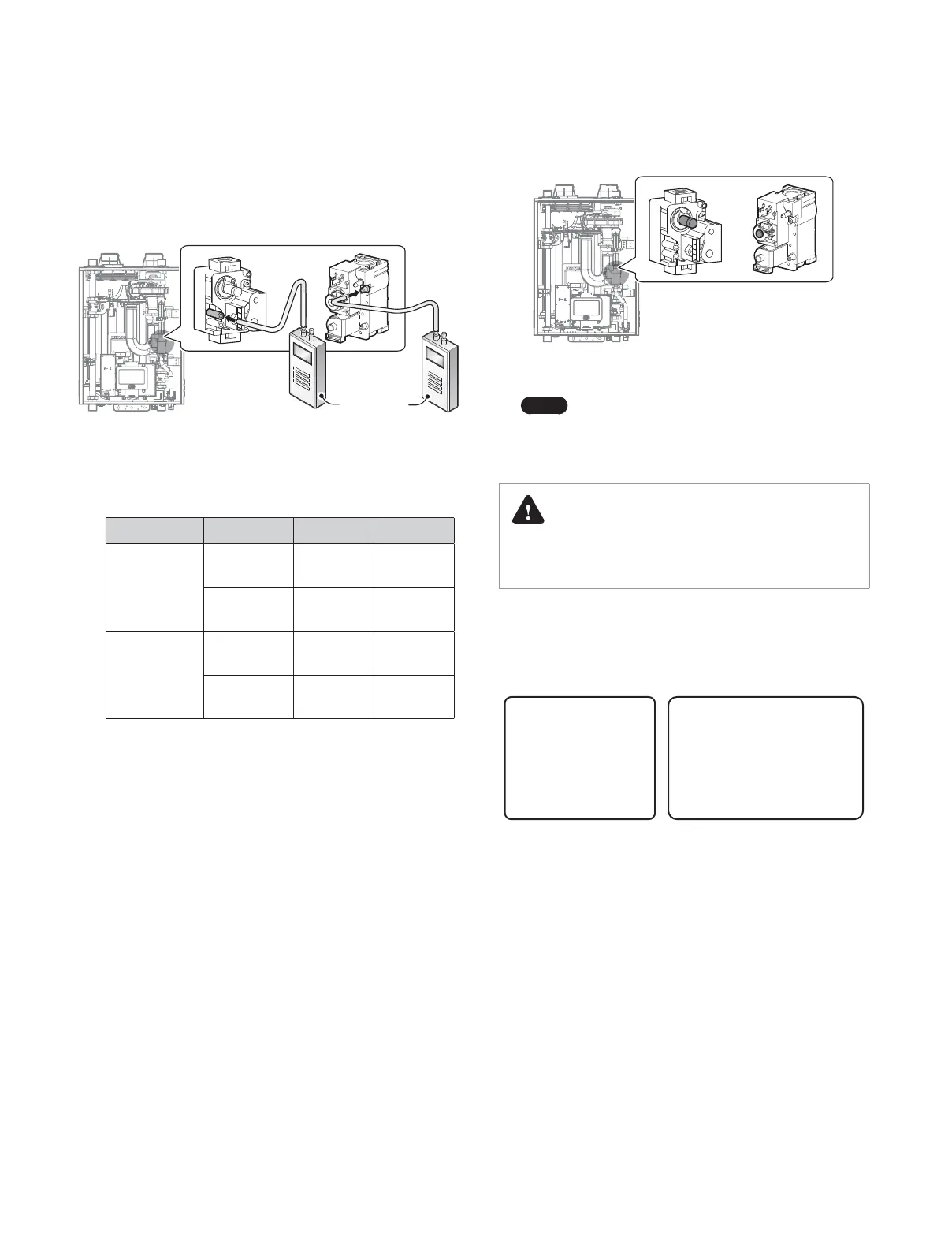
Option 2. Using Digital Manometer
a. Open the offset pressure port by loosening the screw two
turns as shown in Figure 9.
Digital
pressure
manometer
<NFB-399C> <NFB-301C>
Figure 9. Connect Digital Pressure Manometer
b. Connect a manometer to the offset pressure port. For dual
port manometers, use the positive pressure side.
Model Kit Part No. Gas Type Offset
NFB-301C
NAC-NH301 NG
-0.06in
± 0.01in
NAC-LH301 LP
-0.01in
± 0.01in
NFB-399C
NAC-NH399 NG
-0.03in
± 0.01in
NAC-LH399 LP
-0.01in
± 0.01in
Table 3. Offset value for low fire
c. Activate multiple zones and set the boiler to operate at 1Step
MIN mode (refer to “11.6.7 Setting the Operation Modes” on
page 108). Measure the offset value at low fire and compare
it to the values in Table 3. If the offset value is out of range, the
gas valve set screw will need to be adjusted.
If adjustment is necessary, locate the set screw as shown in
Figure 10. Using an Allen or Star Wrench, turn the set screw
no more than
1
/
4
turn clockwise to raise or counterclockwise
to lower the offset value.
<NFB-399C> <NFB-301C>
Figure 10. Set Screw Location
Note
The set screw is located behind the screw-on cover.
This must be removed first.
d. At high fire, do not check the offset value and never adjust
the gas valve.
DANGER
Improper gas valve settings can cause severe personal injury,
death or substantial property damage.
13. Once the CO
2
or offset values have been confirmed, apply the
included conversion stickers to show that the appliance has
been converted to propane gas or high altitude. Place these
labels adjacent to the rating plate as shown in Figure 11.
Orice Size / Injecteur:
Min. 8.65 mm to Max. 17.0 mm
This unit has been
converted to High Altitude (Natural Gas)
Cet appareil a ete converti au Haute altitude (Gaz naturel)
Manifold Gas Pressure /
Pression à la tubulure d’alimentation:
-0.03 inches WC
BTU Input / Debit calorique:
Max. 399,000 - Min. 26,600 BTUh
Conversion Kit No.: NAC-NH399
Inlet Gas Pressure / Pression d'entrée du gaz:
Min. 3.5 to Max. 10.5 inches WC
with Kit No. ________________________
This boiler was converted on
(name and address of organization making
this conversion, who accepts responsibility
for the correctness of this conversion)
______/______/______ to ____________ gas
by _________________________________
_________________________________
Figure 11. Proper Placement of Gas Conversion Labels
 Loading...