23Installing the System Piping
Pressure Relief Valve
To complete the space heating system installation, you must
install a
3
/
4
in pressure relief valve (up to 160 psi max.) on the space
heating hot water outlet. An ASME approved 50 psi HV pressure
relief valve for space heating system is supplied with the boiler.
WARNING
Ɣ
Installing the pressure relief valve improperly may result
in property damage, personal injury, or death. Follow all
instructions and guidelines when installing the pressure
relief valve. The valve should be installed only by a licensed
professional.
Ɣ
The pressure relief valve must be installed at the boiler
outlet and in the vertical position, as shown in this section,
with the drain pipe outlet exiting the side of the pressure
relief valve horizontally and elbowing down.
CAUTION
Install the pressure relief valve as close to the boiler as possible.
No other valve should be installed between the pressure relief
valve and boiler.
When installing the pressure relief valve, follow these guidelines:
Ɣ
Ensure that the valve’s discharge capacity is equal to or greater
than the maximum pressure rating of the boiler’s space heating
system.
Ɣ
Ensure that the maximum BTU/H rating on the pressure relief
valve is equal to or greater than the maximum input BTU/H
rating of the boiler.
Ɣ
Direct the discharge piping of the pressure relief valve so that
hot water does not splash on the operator or equipment.
Ɣ
Attach the discharge line to the pressure relief valve and install
the end of the line within 6-12 in (150-300 mm) above the floor.
Ɣ
Ensure that the discharge line provides complete and
unobstructed drainage. Do not install a reducing coupling or
other restrictions on the discharge line.
If the relief valve discharges periodically, this may be caused by
thermal expansion when the expansion tank is full or undersized.
Do not plug the relief valve.
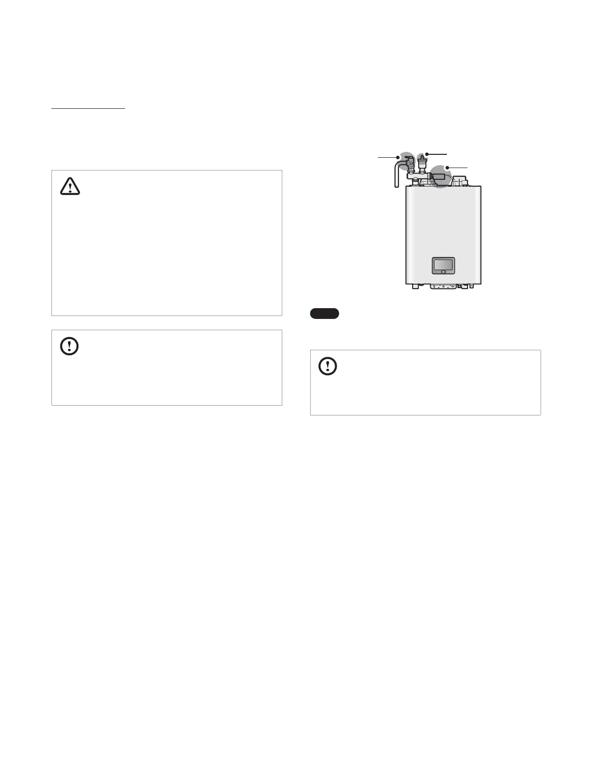
The illustration below shows an example of a pressure relief valve
and an air vent installed with the PRV-air vent adapter included in
the accessory box. Use the included nipple to attach the pressure
relief valve to the adapter.
External LWCO
Air Vent
Pressure
Relief Valve
Note
Depending on the installation conditions, pressure
relief valves (not included and for separate purchase) of
up to 160 psi can be used.
CAUTION
All separately purchased pressure relief valves must be ASME
certified.
 Loading...