33Installing the System Piping
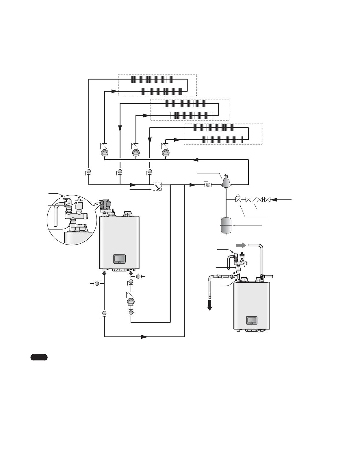
3.5.2 System Application - Zone System with Pumps (Primary/Secondary Piping)
Make-up Water
Backflow preventer
Pressure reducing valve
Additional Zone
Zone #2
Zone #1
Air Separator
Pressure
Relief Valve
Air Vent
Air Vent
Bushing
Boiler Pump
Expansion Tank
Return
Auto Air
vent
Pressure
Relief Valve
Air Vent Busing
Double Nipple
Tee
Supply
<Alternate Top Connections>
Return filter
Note
Ɣ
System application drawings are intended to explain the system piping concept only.
Ɣ
Install a filter in the system return to remove foreign objects from the system. Foreign objects inside the system may result in
abnormal system operation.
Ɣ
Refer to “3.3 Filling the System” on page 29 for make-up water connections and refer to the requirements of your local codes
to ensure compliance.
Ɣ
Use a pump with an integral check valve or install a check valve at the pump outlet.
Ɣ
Refer to “3.6.6 Wiring Diagram - Generic Zone System with Circulators” on page 42 for wiring connections.
Ɣ
Depending on the installation environment, the supply top and return top piping option can be applied.
 Loading...