37Installing the System Piping
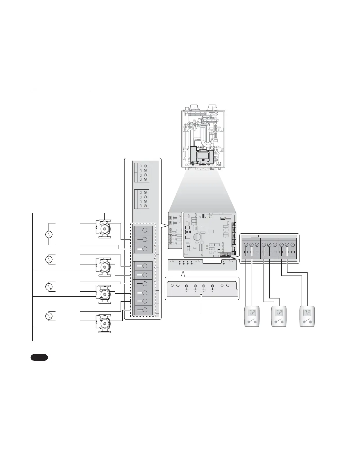
3.6.3 Wiring Diagram - Zone Pump System
The NFB Boilers can operate a heating system with up to 3 zones. The following is the wiring diagram for a zone pump system with 3 zones.
Without 24VAC Connections
18/7,6: )/2:6: /36:
287'225 '+:7$1.
6<67(0
6833/<
6<67(0
5(7851
5:
76=21( 76=21( 76=21(
&
5:
&
5:
&
5:
&
76'+:
/:&2
$&9/
$&91
%RLOHU3XPS
=21(3803 =21(3803 =21(3803
/B,1 /B287/B,1 /B287/B,11&/B287 12/B287 &20/B,1 /B287
%RLOHU6WDWH %RLOHU(UURU$+ '+:35,
%RLOHU3XPS
=21(3803 =21(3803 =21(3803
/B,1 /B287/B,1 /B287/B,11&/B287 12/B287 &20/B,1 /B287
%RLOHU6WDWH %RLOHU(UURU$+ '+:35,
5:
76=21( 76=21( 76=21(
&
5:
&
5:
&
$&9B1
$&9B1
$&9B/
$&9B/
$&9B1
$&9B/
$&9B1
$&9B/
$&
$&
$&
$&
Boiler Pump
Zone Pump 1
Zone Pump 2
Zone Pump 3
Use with dry
contacts only
Pump Ground
Thermostat 1 Thermostat 2 Thermostat 3
Note
The rated output of the provided dry contacts are designed to be 5A/120V per each output.
 Loading...