7 ELECTRONIC CONTROL SYSTEMS DIAGNOSTICS 309
ATA Datalink (American Trucking Association)
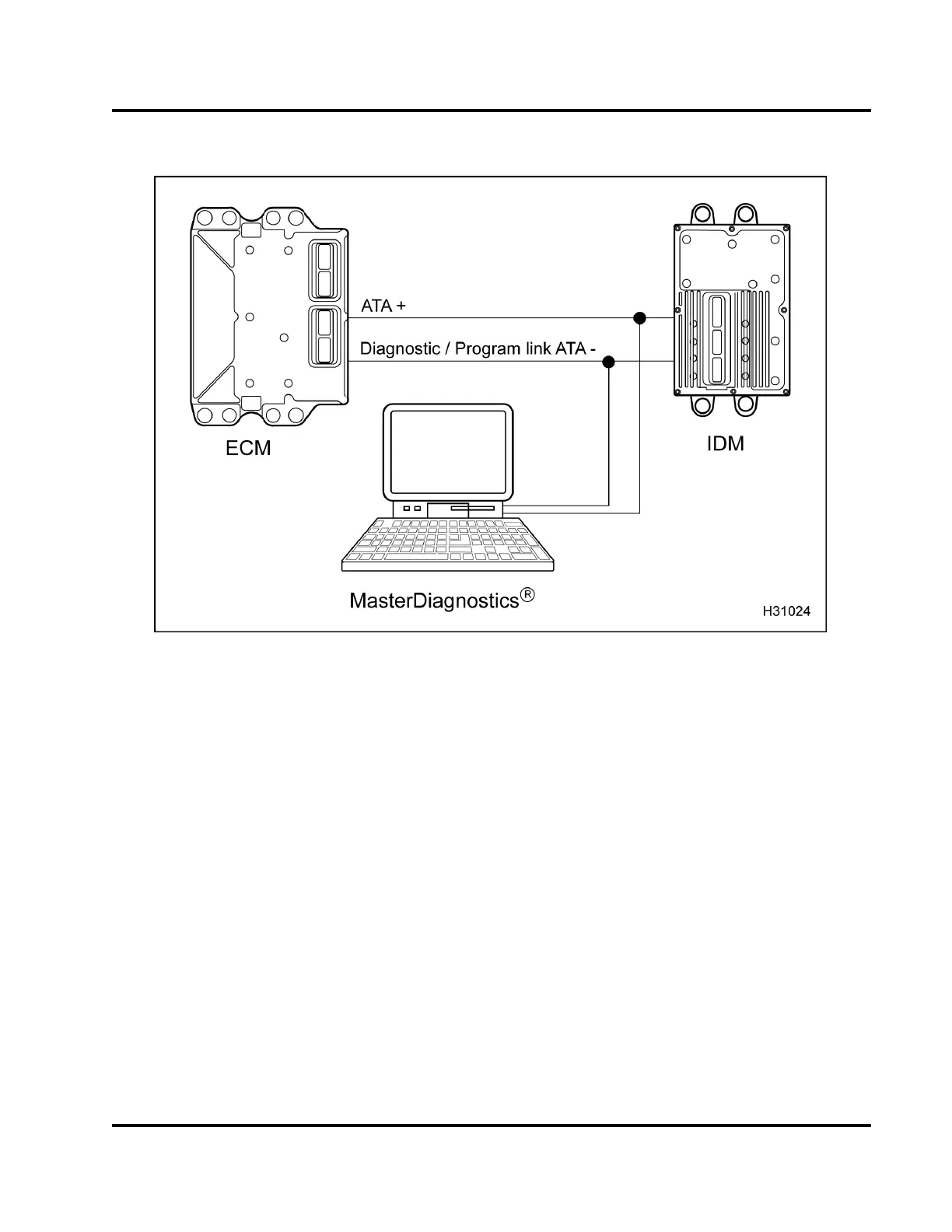
Figure 380 Function diagram for the ATA datalink
The function diagram for the ATA datalink includes the
following:
• EST with MasterDiagnostics® software
• Electronic Control Module (ECM)
• Injection Driver Module (IDM)
Function
The Data Communication Link signal is a 0 V to 5 V
variable width square wave form signal that enables
communication between the MasterDiagnostics®
software and the ECM. The data communication link
also allows for programming the ECM and IDM.
EGES-270-1
Read all safety instructions in the "Safety Information" section of this manual before doing any procedures.
Follow all warnings, cautions, and notes.
© August 2008 Navistar, Inc.
 Loading...