EasyManuals Logo

NAVITUS MCL 5.10 User Manual

NAVITUS MCL 5.10
22 pages
To Next Page IconTo Next Page
To Previous Page IconTo Previous Page
Page #10 background imageLoading...
Page #10 background image
10
- X2 -
1
Reserved
-
2
Reserved
3
RS485 B
In/Out
Meter interface (RS485)
4
RS485 A
In/Out
Meter interface (RS485)
5
CLIN +
In/Out
Client system connection interface (CLIN)
6
CLIN -
In/Out
Client system connection interface (CLIN)
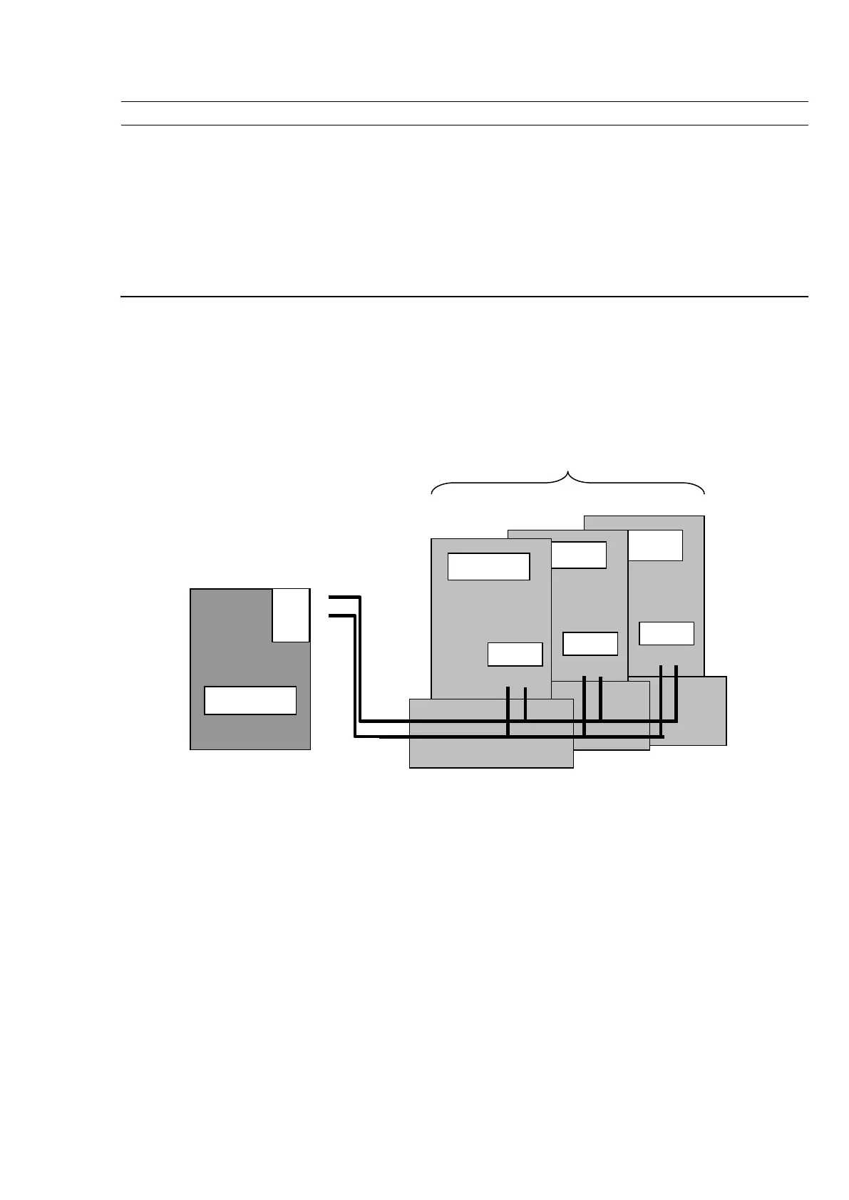
6.1 Connecting a Meter
In order to connect a meter, please connect controller’s X2 connector with a meter’s “A” and “B” socket of the
RS485 interface (see Figure 4.2-1). If there is more than one meter to be connected the parallel method must
be used as indicated below:
7. Labeling
Principal controller information is marked on a label.
Label explanation:
LED indicator position
Controller name
Power supply input and consumption characteristics
Unique identification number (ID)
Unique identification number (Barcode), type: Interleaved 2/5
Figure 4.3.1-1. Meter connection to RS485 interface
123 kWh
125
kWh
124 kWh
MCL 5.10
X1
/
X2
A
RS48
5
B
CL / B
A
RS48
5
B
CL / A
A
RS48
5
B
Meters 1 .. 32, parallel connection method

Questions and Answers:

Question and Answer IconNeed help?

Do you have a question about the NAVITUS MCL 5.10 and is the answer not in the manual?

NAVITUS MCL 5.10 Specifications

General IconGeneral
BrandNAVITUS
ModelMCL 5.10
CategoryController
LanguageEnglish