Do you have a question about the NCR SelfServ 90 R1.2 and is the answer not in the manual?
This document outlines the installation procedures for upgrading the NCR SelfServ 90 (7709) Kiosk's imaging scanner from a Honeywell 7580G to a Datalogic 1500i scanner. The instructions are divided into two main sections, one for R1.2 and another for R2.0 versions of the NCR 7709 Kiosk, reflecting potential differences in the physical layout or cable routing between the two revisions.
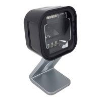
The primary function of this kit is to facilitate the replacement of an existing scanner with a new Datalogic 1500i model, thereby enhancing or maintaining the kiosk's barcode scanning capabilities. The Datalogic 1500i is designed to integrate seamlessly into the NCR SelfServ 90 Kiosk, providing reliable and efficient scanning for various applications, such as retail self-checkout or information retrieval. The kit includes all necessary components for the upgrade, such as the Datalogic Magellan 1500i scanner with a base cover, a USB Type A to RJ50 cable for connectivity, an imager bracket specifically designed for the 7709 kiosk, and various fasteners like serrated nuts and cable ties for secure installation. Additionally, a carton pack with convoluted foam is provided, presumably for safe handling and storage of components during the upgrade process.
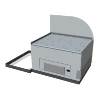
For both R1.2 and R2.0 installations, the initial steps emphasize safety and proper kiosk access. Users are explicitly warned to disconnect the AC power cord before disassembling the kiosk to prevent electrical hazards. The procedure then details how to safely open the kiosk's front panel by inserting a key into the lock and turning it clockwise. A crucial caution is provided to prevent abrupt opening and releasing of the kiosk front, advising users to hold and support it until fully extended. This highlights a key usage feature: the kiosk's design allows for front access for maintenance and upgrades, but requires careful handling to prevent damage.
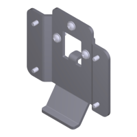
The removal process for the old Honeywell 7580G Imaging Scanner involves several steps. First, the imaging scanner cable must be disconnected from the motherboard. This step is critical for isolating the component and preparing for its removal. Following this, any cable ties securing the cables routed on the imaging scanner bracket need to be cut. This indicates a maintenance feature where cables are neatly organized and secured within the kiosk, requiring their release for component removal. Finally, three nuts securing the imaging scanner to the kiosk are removed, allowing the old scanner to be lifted out of its mounting area. This suggests a standardized mounting mechanism that simplifies replacement.
The installation of the new Datalogic 1500i Imaging Scanner assembly is a reverse and complementary process. The new imaging scanner is first mounted onto the imager bracket. The instructions stress the importance of ensuring that the scanner sits tightly into the slot, indicating a precise fit designed for stability and optimal performance. Subsequently, the imaging scanner assembly is mounted over the imager shield. An important note highlights the need to ensure that all sides of the imager scan window are flush against the sides of the imager shield on the front side of the fascia. This detail is crucial for proper alignment, which directly impacts the scanner's ability to read barcodes effectively and ensures a clean aesthetic integration with the kiosk's exterior. Adjustments to the imager's alignment are advised if necessary, underscoring the importance of precision during installation. Once properly aligned, the assembly is secured to the kiosk using three nuts, mirroring the removal process of the old scanner.
Connectivity is another vital aspect of the installation. The imaging scanner cable is connected at one end to the bottom of the imaging scanner and at the other end to the USB B port of the motherboard. This establishes the data and power connection for the new scanner. A significant part of the installation involves cable management. The instructions specify routing and tucking the imager USB cable, printer USB and power cable, and I/O adapter power cable together on the left side of the imaging scanner assembly. These cables are then secured to a designated cable management slot using a cable tie. This emphasizes a maintenance feature aimed at keeping the internal wiring organized, preventing interference, and facilitating future servicing. Proper cable routing is essential for the longevity of the cables and the overall reliability of the kiosk.
The distinction between R1.2 and R2.0 procedures primarily lies in the visual aids and potentially minor variations in cable routing or component placement, though the core steps remain consistent. The document's structure, with clear warnings, cautions, and important notes, guides the user through a safe and effective upgrade process. The inclusion of part numbers for each component in the kit is a practical feature, aiding in inventory management and ensuring that all necessary items are present before commencing the upgrade. The overall approach is methodical, ensuring that even users with moderate technical skills can perform the upgrade successfully. The focus on precise alignment and secure fastening reflects the need for robust and reliable operation in a public-facing kiosk environment.
| Model | SelfServ 90 R1.2 |
|---|---|
| Type | Rack |
| Brand | NCR |
| Material | Steel |
| Color | Black |
| Compatibility | NCR SelfServ 90 |