Issue 2 December 1995 4-5
Connect the MCI Line to the Switch
2. Set the parity of the MCI link to even and the word length to 7 bits.
Use Table 4-2 and Table 4-3 to set the DIP-switches on the MCI I/O card
in the switch.
If you need more information for setting the baud rate, parity, and
DIP-switches on the NEAX 2400 MCI port, refer to the
documentation supplied with your switch or contact your switch
service representative.
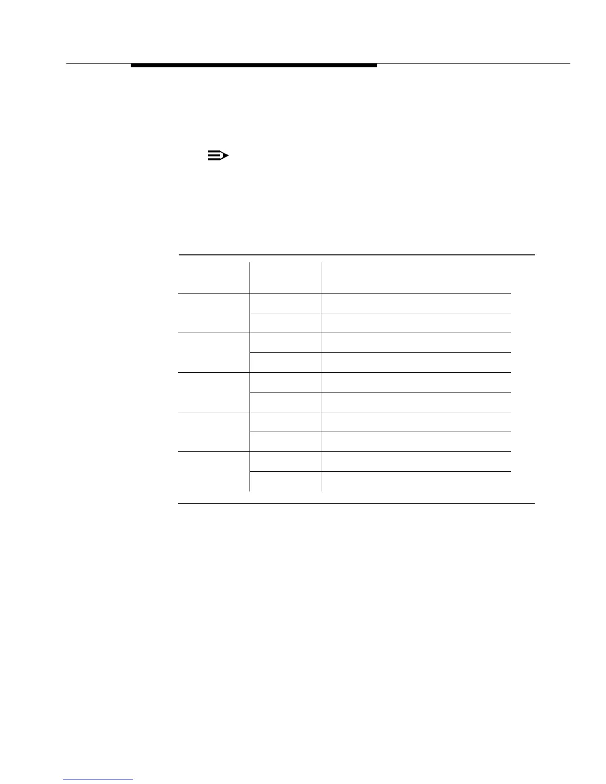
Table 4-2. MCI I/O Port DIP-Switch SW01 or SW11 Settings for Switches 4
through 8
Switch
Number
Setting Function
4
ON Parity bit valid
OFF Parity bit invalid
5
ON Odd parity
OFF Even parity
6
ON 7 bits
OFF 8 bits
7
ON 1 stop bit
OFF 2 stop bits
8
ON Send side FIFO is 1 byte
OFF Send side FIFO is 64 bytes