7-3
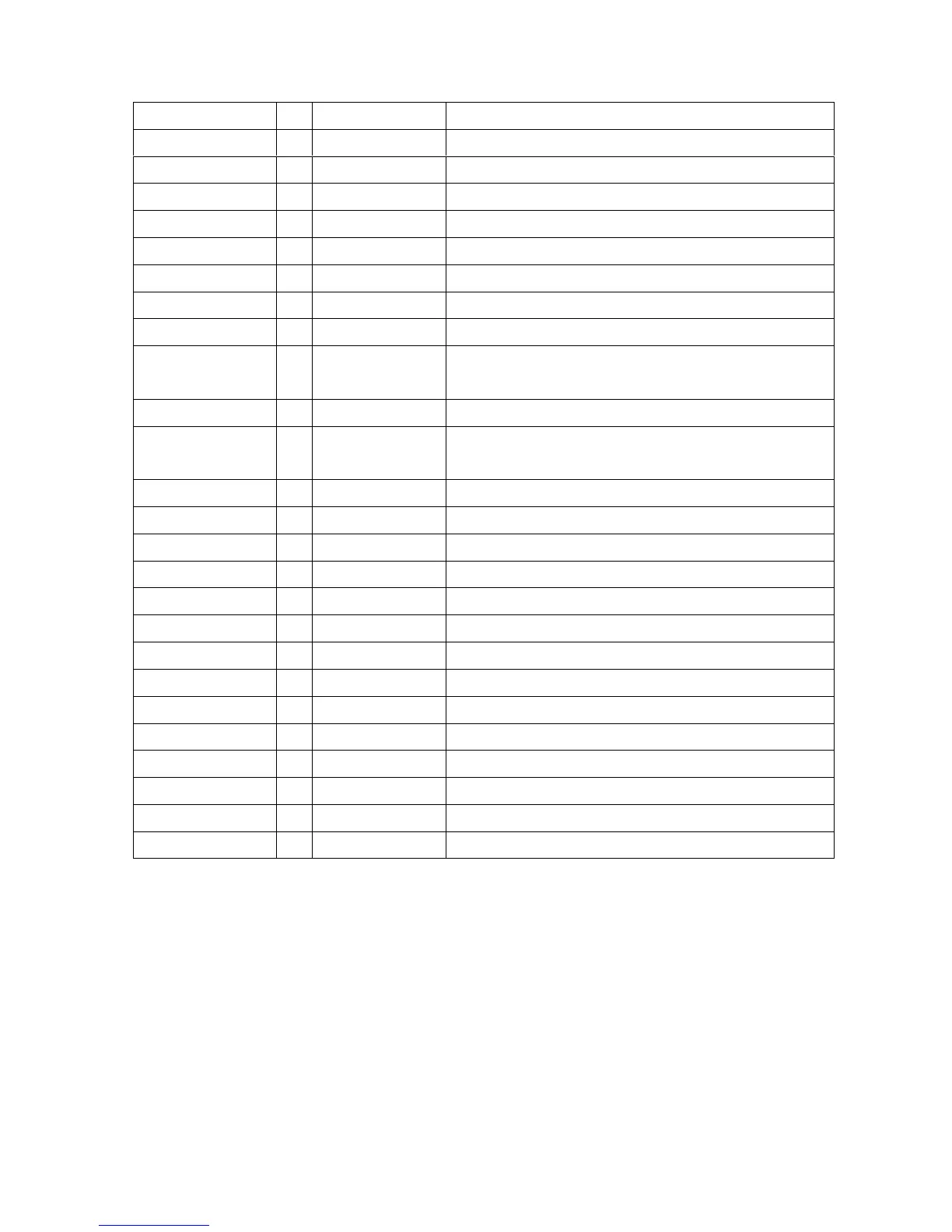
Pin name I/O NO Describe
RED+ I 77 Positive analog input for RED channel
RED- I 78 Negative analog input for RED channel
GREEN+ I 74 Positive analog input for GREEN channel
GREEN- I 75 Negative analog input for GREEN channel
BLUE+ I 70 Positive analog input for BLUE channel
BLUE- I 71 Negative analog input for BLUE channel
HSYNC I 95 ADC input horizontal sync
VSYNC I 96 ADC input vertical sync
TCLK I 88
Reference clock from the crystal oscillator or external
MCU source
XTAL O 87 Crystal oscillator output
RESETn I 90
Hardware Reset signal I/O is active low output (120ms)
provided for other system components
PBIAS O 29 Panel Bias Control (backlight enable)
PPWR O 30 Panel Power Control
GPIO1/PWM1 O 53 Volume Control
GPIO1/PWM1 O 52 Panel Backlight Control
CLKP_LV_E O 7 LVDS Clock+
CLKP_LV_E O 8 LVDS Clock-
AVDD_RPLL_33 I 89 Analog power (3.3v) for the reference DDS PLL
VDD_RPLL_18 I 84 Digital power (1.8v) for RCLD and clock generator
VDDA_ADC_33 I 69/79 Analog power (3.3v) for the ADC
VDD_ADC_18 I 82 Digital power (1.8v) for ADC encoding logic
AVDD_LV_33 I 1 Analog 3.3v supply for LVDS PLL and Band gap
AVDD_OUT_LV_33 I 4/16/28 Digital 3.3v supply for LVDS outputs
RVDD_33 I 33/51/94 Ring VDD (3.3V)
CVDD_18 I 31/47/65/67/92/99 Core VDD (1.8V)