7-5
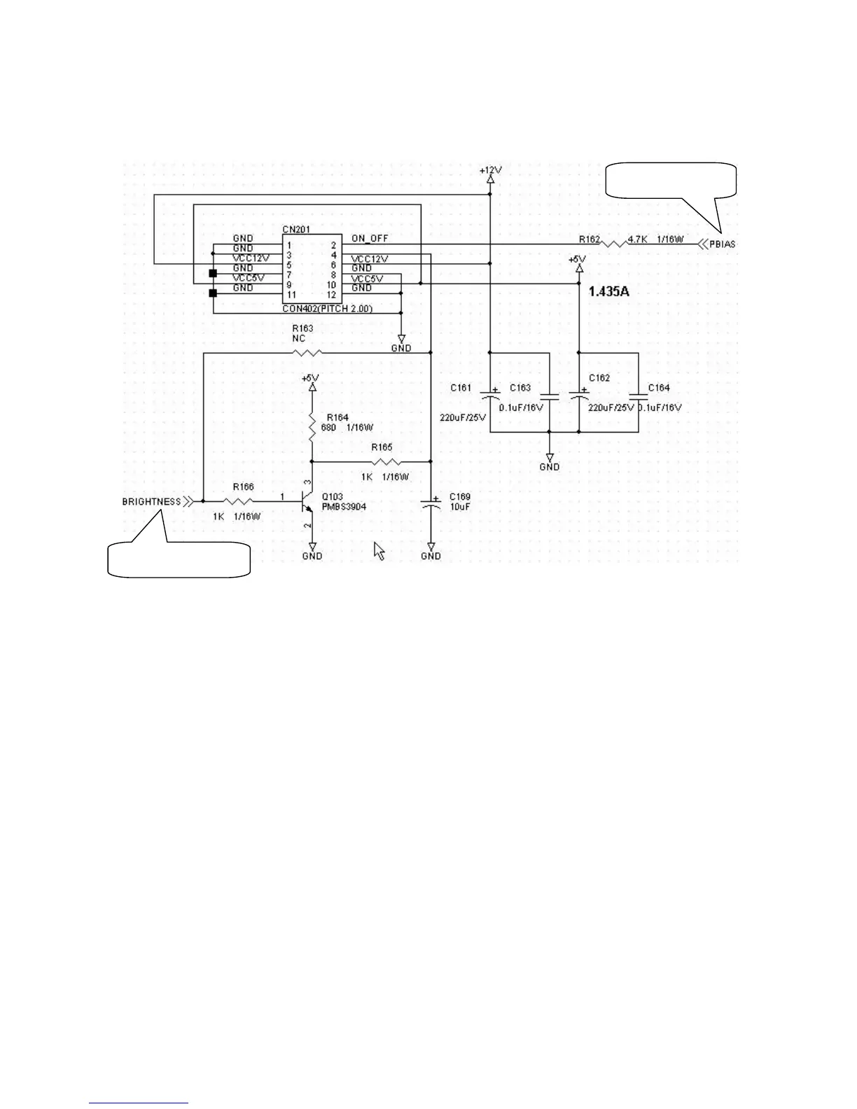
2.6 On/Off /Brightness control circuit
ON/OFF control: When engaged, the outputs are high level, and low in saving energy state.
Brightness control: When engaged, the output PWM pulse from PIN 52 of U101 adjusts the brightness, the
smaller the duty cycle, the higher the brightness.
3. PWPC
PWPC board combines an adapter and inverter.
The adapter consists of bridge rectifier, filter, start circuit, PWM control circuit (SG6841D), and protection
circuits. It provides 12V, and 5V DC voltage from input of 90V-240V AC voltage. It provide power supply for each
chips in the main board and inverter.
The inverter is DC TO AC circuit. It changes the 12v DC of power supply to about 600-800v AC which drives the
backlight. It consists of starting circuit, PWM controller, DC changing circuit, LC surging circuit, output circuit and
protection circuit.
3.1 Adapter
EMI filter circuit: It is used to get rid of the disturbance existing in the electric network or spuriously coming
from outside. L902 is used to reduce the symmetry disturbance and filter high frequency noise. C901, and C902
can control the symmetry, and filter the low frequency noise. R901, and R902 is used for discharging the
capacitance when the power is off. NR901 is used to prevent the pulse of surge current at start-up.
ON/OFF control
Brightness control