7-10
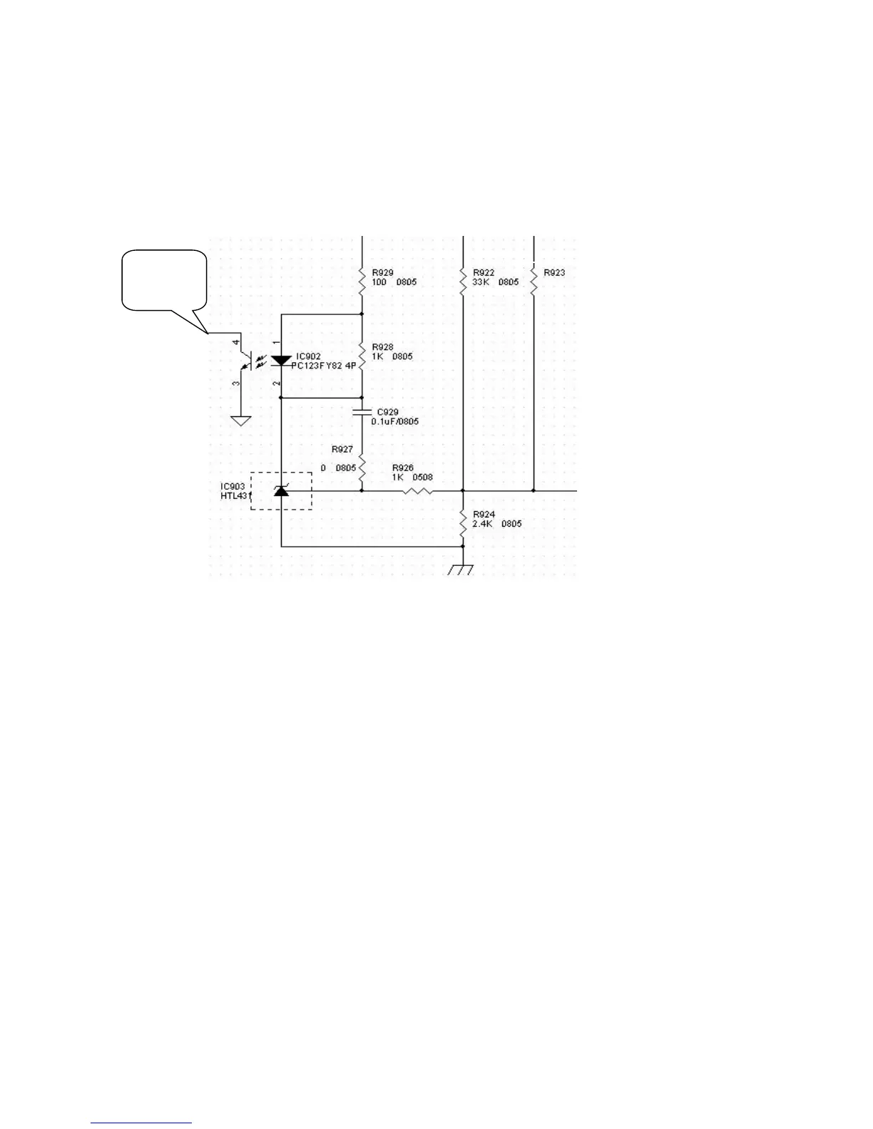
Circuit for steadying voltage: The rising of electric supply voltage can result in the increase of output voltage.
This leads to the increase of the current that flows through photoelectric coupling unit. The brighter the light
produced inside the photoelectric coupling unit, the more easily the current can get through the photosensitive
side, due to it lower resistance. That’s the reason for the decrease of voltage at PIN 2. When the voltage is
applied to the reverse-phase terminal of error amplifier inside SG6841D, It controls the duty of pulse output and
reduces the voltage output. This process stabilizes the output. As the voltage decreases, the same principle
is applied to steady the output.
12V
12V
TO U201
PIN2
5V