GWP-G22996
3 - 18
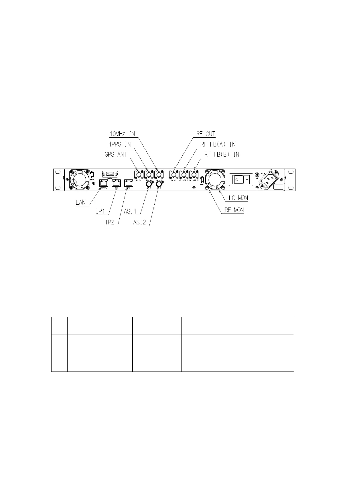
3-7-2 Signal Line
In this transmitter connect various signal lines (ASI, 1PPS, 10MHz, etc.) to rear
panel of exciter directly. The standard rear panel layout of exciter is shown in Fig. 3-8.
The interface board is mounted on the rear side of the TX control.
Fig. 3-8 Rear view of exciter
3-7-3 RF Monitor (See Table 3-7)
Table 3-7 Connectors for 50Ω RF Monitor
No. Item
through
Remarks
1 TX MON J110
The output power of the transmitter (after
BPF).
This connecter is attached to the front of
 Loading...