GWP-G22996
3 - 20
3-7-4-1 Parallel Interface
The connection of the parallel interface with remote control equipment is made
using interface board connectors (J1 and J2). The control items are listed in
Table 3-9
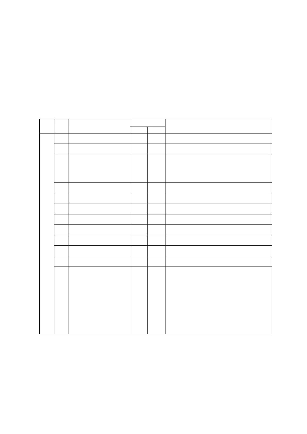
Table 3-9 Connectors for Remote control
(Interface Board J1 to Remote control Equipment)
Use No. Item
Description
COMMAND
1 TX ON CONT 1 15/16 ON command from remote control unit.
2 TX OFF CONT 2 15/16 OFF command from remote control unit.
3 TX RESET 3 15/16 Upon occurrence of a fault, hold status
indication of transmitter and OFF status
indication sent out to remote site is released.
4 EX-A Select (*1) 4 15/16 Command to select the exciter-A
5 EX-B Select (*1) 5 15/16 Command to select the exciter-B
6 PUMP-A Select (*2) 6 15/16 Command to select the PUMP-A
7 PUMP-B Select (*2) 7 15/16 Command to select the PUMP-B
8 H. EXC-A Select (*3) 8 15/16 Command to select the H.EXC-A
9 H. EXC-B Select (*3) 9 15/16 Command to select the H.EXC-B
10 AUTO ON CONT 10 15/16 ON command by external equipment.
11 AUTO OFF CONT 11 15/16 OFF command by external equipment.
12 R/C OFF 12 15/16 When in the remote mode, in case of remote
control line failed, the R/C OFF signal
entered into TX control.
The DIP switch of TX control set as below
starts or stops the TV transmitter.
SW6-7(ON) : TX ON effective
SW6-8(ON) : TX OFF effective
 Loading...