l-1. Switching regulator unit
(a)
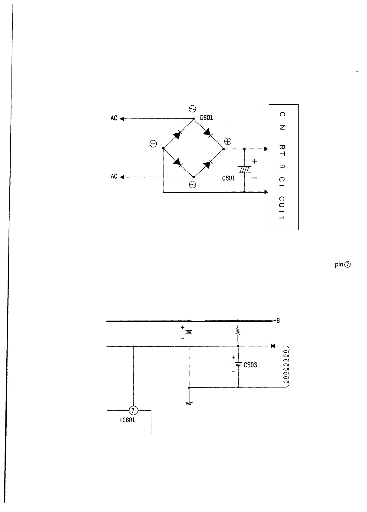
Rectifying
and-filtering circuit
AC input is rectified by
D601.
Then, it is filtered by
C601.
The resulting DC voltage is supplied to the
’
converter
circuit.
(Fig l-i -1) Rectifying and Filtering Circuit
(b) Auxiliary power supply circuit
0
0
z
C
m
fl
m
zu
0
-
A
0
c
-
-I
The auxiliary power supply circuit is needed to activate
IC601.
At the time when the power is turned on, the
charging current flows into the capacitors
C603
via R601. Oscillation starts when the voltage of
IC601
pin@
reaches
16V
by this charging operation.
After the start of oscillation, the
flyback
voltage of the auxiliary winding for the switching transformer is
rectified and filtered by
D608
and
C603.
The resulting DC voltage is supplied to
IC601.
C601
4
R601
D608
(Fig l-1 -2) Auxiliary Power Supply Circuit
36