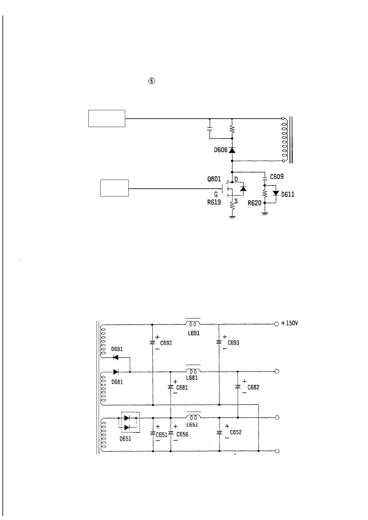
(c) Converter circuit
The
converter circuit consists of the primary winding of the switching transformer T601, a switching device
Q601,
and surge absorbers (C602, R602, C609, R620, D606, and D611) that are connected to the primary
winding.
The oscillating signal-from
IC601
pin
@
is applied to the gate of Q601 causing the drain-source to be turned
OFF and ON so that the oscillating voltage is applied to the primary winding of T601.
FILTERING
T601
CIRCUIT
C602
f
R602
From
IC601
Pin@_
DRIVE
CIRCUIT
(Fig
l-1-3)
Converter Circuit
(d) Output rectifying circuit
The
flyback
voltages generated at the secondary windings of the switching transformer T601 are rectified
by
D651,
D681,
and
D691.
Then, these voltages are filtered by C692, C693,
C651,
C652, C656,
C681,
and
C682 so that rectified DC voltages are obtained.
Constant
flyback
voltages are maintained by controlling the duty cycle of Q601 in the
converter circuit.
T601
..___......
+
80V
+24V
GNO
(Fig l-1 -4) Output rectifying Circuit
37