(e)
Error
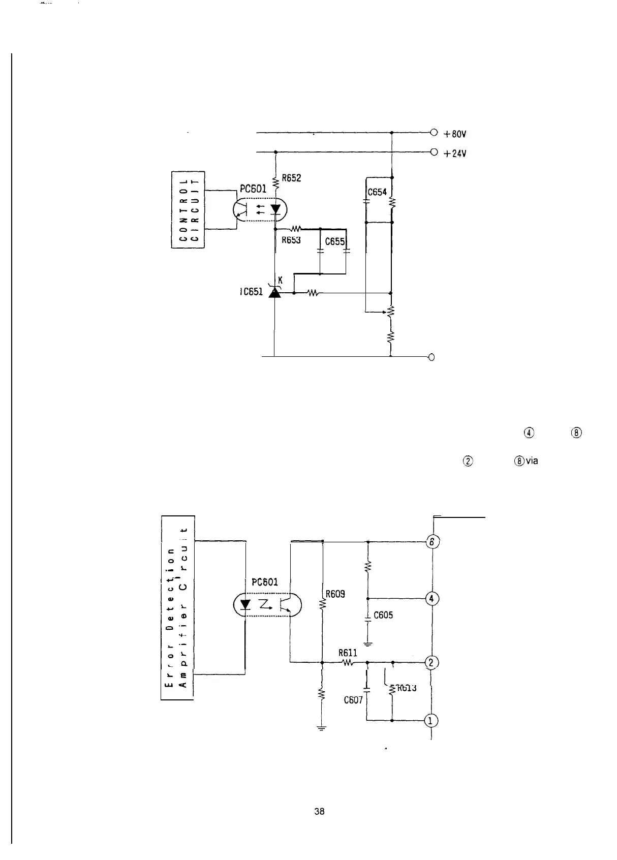
detection amplifier circuit
The output voltage 80V is divided by the network resistors. This divided voltage is compared to the reference
voltage at the error amplifier
lC651.
An error signal is applied to the control circuit via the photocoupler
PC601.
R655
C653
0
A R
R654
-
VR651
R654
0
GND
(Fig l-l-5)
Error Detection Amplifier Circuit
(f)
Oscillating and control circuit
The oscillating, control, and drive circuits are contained in
IC601.
IC601
has a built-in oscillator whose frequency is determined by R608, and
C605
connected to pin @ and pin
@J
respectively.
The output of the error detection amplifier circuit is fed back to the control circuit pin
@ from pin
@via
PC601 to
control the duty cycle of
Q601
so that output voltages are kept constant.
r’
00
.-
I
.-
0
R608
_,.1_.
’
c--r
L.
e
wu
/
I
I
I__._
i
R612
I
C601
(Fig l-l-6) Oscillating and Control Circuits