(g)
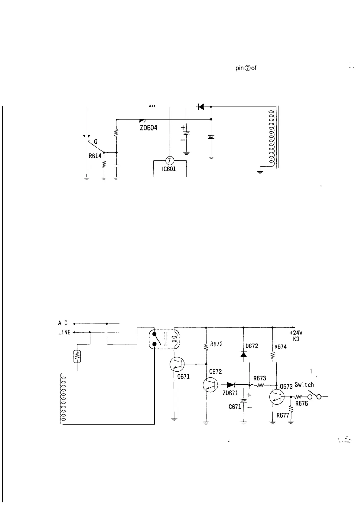
Overvoltage Protection
If a failure occurs and the output voltage on the secondary winding rises, the voltages of the auxiliary
winding will also rise proportionally. When the auxiliary windings voltage rises beyond the zener voltage of
ZD604, CR602 will turn ON. This in turn will decrease the voltages at
pinaof
IC601
causing the oscillator
within
IC601
to stop.
CR602
7
K
411
R605
0615
r)
1,
A
C603
+
r
R610
ap:
C606
-
C621
D608
T601
(Fig 2-l -7) Over Voltage Protection
(h) Auto and Manual Degaussing circuit
1)
2)
Auto Degaussing Circuit
When the unit is turned ON. The
+24V
DC output at k3 rises. This will cause 0671 to turn ON. The ON
period for this transistor is determined by R673, ZD671, R674, and C671 (approx. 2 seconds). When 0671
is ON, current will flow through the Degaussing Coil
Manual Degaussing Circuit
When the Degauss Switch is turned ON, 0673 conducts thereby discharging C671, When C671 is
discharged, Q671 will turn on again.
$
TH601
I
Degaussing
Coi I
Manua
I
r&;
!
Rd
Q673
Switch
’
Degaussrng
1~67y
_;
=
(Fig l-l -8) Auto and Manual Degaussing Circuit
39