4. Digital Control System
4-1. Digital Control Circuit
The following items are controlled by the Digital Control System.
Digital Control System
-
Automatic Synchronization
-
Management of proper picture display
-
Management of the user controls
-
Management of the color correction
-
Management of the side pin data
-
Management of the factory adjustment
Automatic Signal Identification
Automatic Sizing
Automatic Centering
Memory of Picture Data
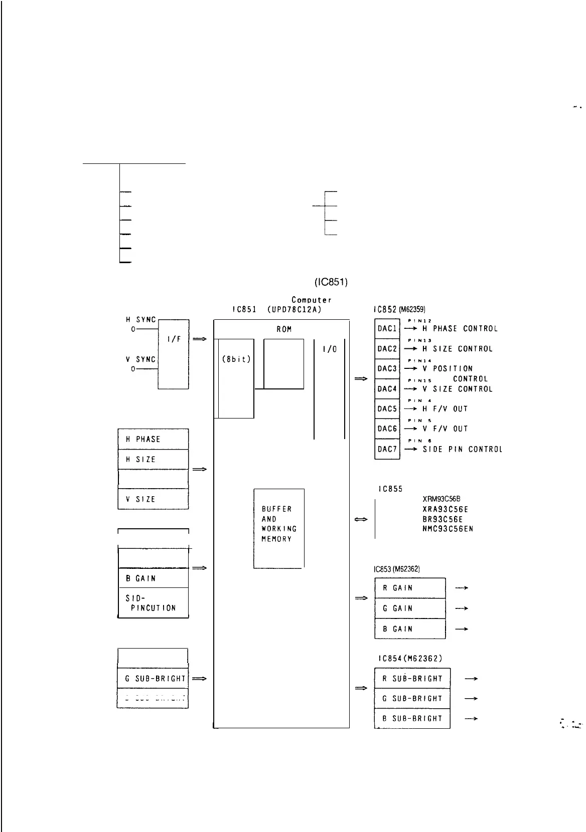
The relationship of the input and the output of CPU
(IC851)
is shown on Fig. 4-l-l
Model USER
CONTROLS
V POSITION
Mode2
R GAIN
I
G CAIN
-
B
CAIN
SIO-
PINCIJTION
Mode3
R SUB-BRIGHT
B SUB-BRIGHT
Single Chip
Computer
lC851
(UPD78ClZA)
CPU PROGRAM
(8bit)
MEMORY
ROM
RAM
1
/o
D/A Converter
lC852
(M62359)
EEPROM
lC855
7
XRM93C55B
XRA93C56E
OR
BR93C56E
OR
NMC93C56EN
Multiplier D/A Converter
lC853(M62362)
lC854(M62362)
(Fig 4-l-l) The BLOCK DIAGRAM of Digital Control System
55
-.
_
*
--.
e.
._