5-l-2. Horizontal phase circuit
-
.
USER
H POS
CONTROL
Ica52
M62359
’
gv
mA7
~47650
R5A9
L-
ADJUST
I
CIRCUIT
I
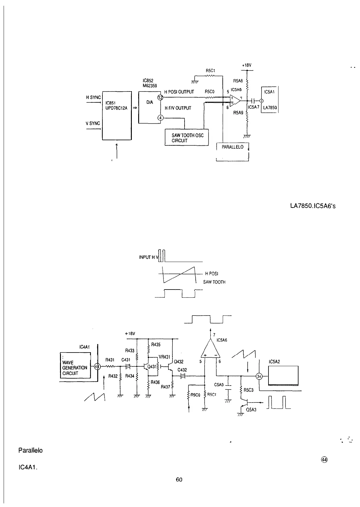
(Fig 5-l-2) BLOCK DIAGRAM of the H phase circuit
Horizontal Position is to be adjusted by delaying the Horizontal Sync signal phase input to
LA7850.
IC5A6’s
inputs of H position control voltage and saw tooth waveform are generated from the H sync timing. The duty
comparator’s output varies with the H position control voltage. The sync signal phase can be delayed by
triggering to LA7850 on the breaking edge.
INPUTHV
1
1
-b+
S::oisdOTH
WAVE
I
-
._...I
L-J
OUTPUT COMPARATOR
TRIGGER
SAW TOOTH
lC5A2
CONSTANT
CURRENT
CIRCUIT
t
J7-
H POS control voltage
4--
C15A3
IL-IL
(Fig 5-l -3) PARALLEL0 DISTORTION correct circuit and SAW TOOTH OSC circuit
.
Parallel0
distortion is corrected by the H Position control voltage that varies with the sawtooth waveform pulse of
vertical timing through C432, and is adjusted with VR431. This sawtooth waveform pulse is produced at pin @ of
IC4Al.
.
.-_
.
I
60