English-25
English
TILE MATRIX Allows one image to be expanded and displayed over multiple screens (up to 100) through a
distribution amplifi er.
NOTE: Low resolution is not suitable for tiling to a large number of monitors. You can operate
without a distribution amplifi er at a lower number of screens.
NOTE: This function is released when selecting IMAGE FLIP except for NONE.
Dynamic or Zoom will not work when Tile Matrix is activated.
When “DYNAMIC” or “ZOOM” is selected in ASPECT while executing TILE MATRIX, the setting
will be applied after completing of TILE MATRIX.
H MONITORS Number of monitors arranged horizontally.
1
V MONITORS Number of monitors arranged vertically.
1
POSITION Select which section of the tiled image to be displayed on the monitor.
1
TILE COMP Turns the TILE COMP feature on. NO
TILE MATRIX ENABLE Enables Tile Matrix. NO
FRAME COMP
(not adjustable)
V SCAN REVERSE
(not adjustable)
TILE MATRIX MEM When “INPUT” is selected, TILE MATRIX setting is applied to each signal input. COMMON
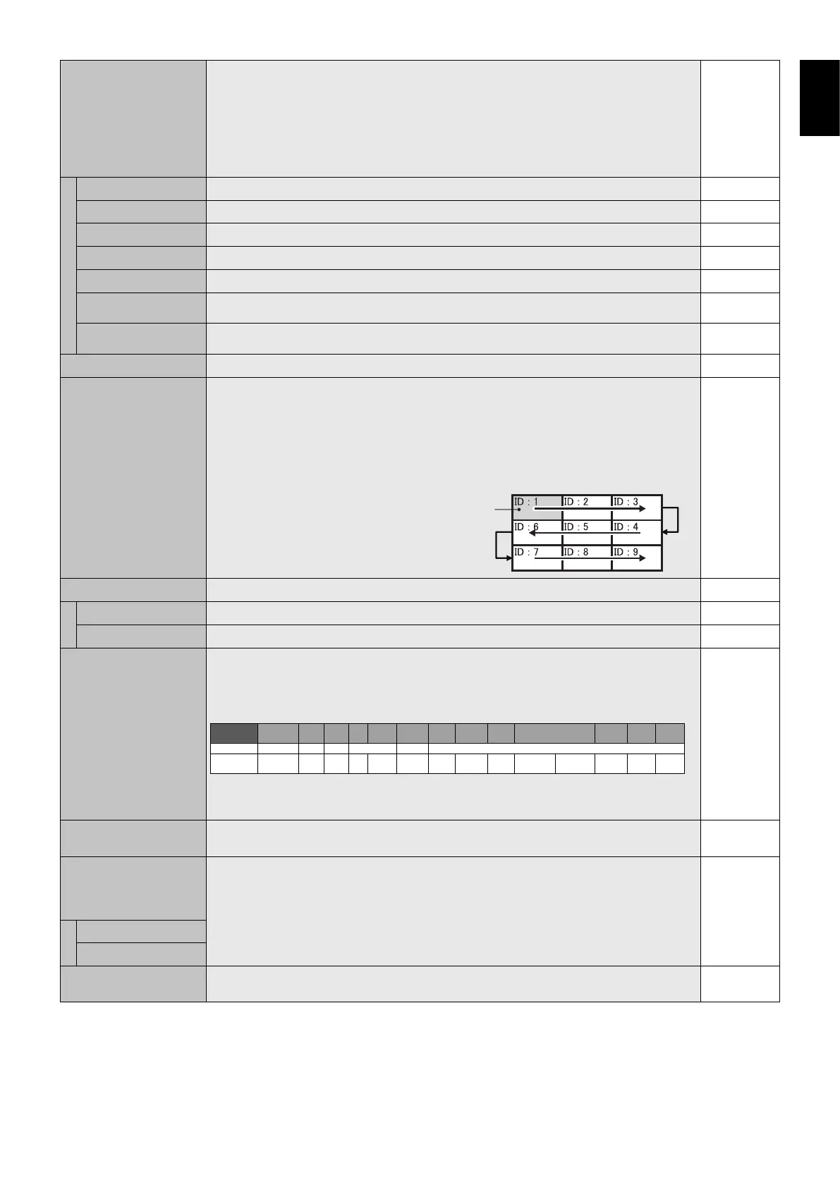
AUTO TILE MATRIX
SETUP
Allows auto setting of multiple screens by inputting the number of monitors arranged horizontally
and vertically on the primary monitor. Following settings are set automatically: MONITOR
ID, TILE MATRIX, TILE MATRIX MEM, Input Signal, VIDEO OUT SETTING, DisplayPort in
TERMINAL SETTING.
NOTE: All monitors which follow in the chain with LAN should be ON. When executing this
function while in standby mode or power save mode, “LAN POWER” should be set to ON.
AUTO ID will be automatically executed. When you use this function, it is recommended that
monitors are chained by DisplayPort cable.
Example of installation via LAN:
H MONITORS 3
V MONITORS 3
Primary monitor
DEACTIVATE
POWER ON DELAY Adjusts the delay time between being in “standby” mode and entering “power on” mode.
DELAY TIME “POWER ON DELAY” can be set between 0 and 50 seconds. 0 SEC.
LINK TO ID When “ON” selected, delay time is linked with Monitor ID. It takes more time as larger ID number. OFF
VIDEO OUT SETTING Enables the signal output from DPORT. See also page 27 “DisplayPort” in TERMINAL SETTING.
NOTE: When VGA or Y/Pb/Pr is selected as the main picture, nothing will be output from DPORT.
When this function is ON, DPORT cannot be selected as the sub picture. When this function is
ON, INPUT CHANGE is limited to be NORMAL or QUICK. When this function is ON and DPORT
is selected as the main picture, PIP CHANGE button of remote control (see page 11) is disabled.
Input signal
name*
1
DPORT
DVI
HDMI
VGA
Y/Pb/Pr
OPTION
VIDEO
S-VIDEO
SCART
Y/Pb/Pr2
RGB/HV
HDMI2
HDMI3
Connector
DisplayPort
DVI-D
HDMI
D-Sub
SLOT2
SLOT3
DP OUT
Yes
Yes
Yes
Yes
—
(SB3-AB1)
Yes
(SB3-AB2)
Yes
*1:
Main picture in PIP (Picture in Picture) mode.
Main picture in PIP (Picture in Picture) mode.
*2:
When you use HDMI OUT connector in SB3-DB1, multicple monitors connection is available.
When you use HDMI OUT connector in SB3-DB1, multicple monitors connection is available.
When you use DPOUT for HDCP authentication signal, Input signal name should be DPORT.
When you use DPOUT for HDCP authentication signal, Input signal name should be DPORT.
Multiple monitors that are daisy-chained have a limit to the connectable monitors.
Multiple monitors that are daisy-chained have a limit to the connectable monitors.
ON
POWER INDICATOR Turns ON or OFF the LED located at the front of the monitor.
If “OFF” is selected, LED will not light when the LCD monitor is in active mode.
ON
SETTING COPY In a daisy chain scenario, select the OSD menu categories that you want to copy over to the
other monitor.
NOTE: When you use this function, monitors should be daisy chained by LAN. This function
resets to default when power is off. This function has a limit depending on the cable you use.
NO
COPY START Select “YES” and press the SET button to start copying.
ALL INPUT All input terminals settings are copied when you select this item. Default is off.
RESET Resets “MULTI DISPLAY” options back to factory settings except for POWER ON DELAY and
VIDEO OUT SETTING.
-