4
P
C
C
A
R
D
L
A
M
P
S
T
A
T
U
S
P
O
W
E
R
O
N
/
S
T
A
N
D
B
Y
S
O
U
R
C
E
A
U
T
O
A
D
J
U
S
T
3
D
R
E
F
O
R
M
S
E
L
E
C
T
P
C
C
A
R
D
L
A
M
P
S
T
A
T
U
S
P
O
W
E
R
O
N
/
S
T
A
N
D
B
Y
S
O
U
R
C
E
A
U
T
O
A
D
J
U
S
T
3
D
R
E
F
O
R
M
L
E
N
S
S
H
I
F
T
L
E
F
T
R
I
G
H
T
DOWN
U
P
P
C
C
AR
D
L
A
M
P
S
T
A
T
U
S
P
O
W
E
R
SOURCE
AUTO AD
JUST
3D REFORM
ON/STAND BY
S
E
L
E
C
T
P
C
C
AR
D
L
A
M
P
S
T
A
T
U
S
P
O
W
E
R
SOURCE
AUTO AD
JUST
3D REFORM
ON/STAND BY
LE
NS S
HIFT
LEFT
RIG
HT
D
OWN
UP
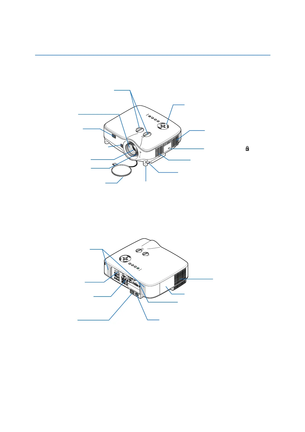
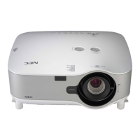
1. Introduction
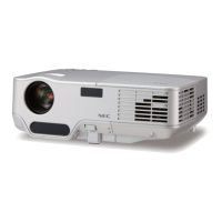
Part Names of the Projector
Controls
(
→
page 7)
Built-in Security Slot ( )*
Zoom Lever
(
→
page 29)
Lens Cap
Remote Sensor
(
→
page 10)
Focus Ring
(
→
page 29)
Lens Shift Dial (Right / Left,Up / Down)
(
→
page 28)
Adjustable Tilt Foot Lever
(
→
page 30)
* This security slot supports the MicroSaver® Security System. MicroSaver® is a registered trademark of Kensington
Microware Inc. The logo is trademarked and owned by Kensington Microware Inc.
Ventilation (inlet) / Filter
(
→
page 108)
Adjustable Tilt Foot
(
→
page 30)
Lens
Front/Top
Ventilation (inlet) / Filter
(
→
page 108)
Stereo Speaker (5W x 2)
AC Input
Connect the supplied power cable's three-pin plug here,
and plug the other end into an active wall outlet.
(
→
page 23)
Main Power Switch
When you plug the supplied power cable into an active
wall outlet and turn on the Main Power switch, the
POWER indicator turns orange and the projector is in
standby mode.
(
→
page 24)
Remote Sensor
(
→
page 10)
Ventilation (outlet)
Heated air is exhausted from
here.
Rear
Terminal Panel
(
→
page 8)
Screw for PC Card Lock
Lamp Cover
(
→
page 110)
LENS RELEASE Button
(
→
page 115)