PASOLINK
+
155 MB 1+0/1+1 SYSTEM MTD-PL-028/141005
- 26 -
1+1 Equipment
LED indication Condition Color
MAINT During maintenance Yellow
ODU ALM1 ODU No.1 Equipment fail Red
IDU ALM1 IDU No.1 Equipment fail Red
ODU ALM2 ODU No.2 Equipment fail Red
IDU ALM2 IDU No.2 Equipment fail Red
PWR1 No.1: On power Green
PWR2 No.2 : On power Green
TX1 No.1 TX output Green
TX2 No.2 TX output Green
RX1 No.1 RX selected Green
RX2 No.2 RX selected Green
Note: The same fails of No.1/No.2 indicate IDU ALM1 and IDU ALM2 at the same time.
TX1/2 and RX1/2 indication available only in case of 1+1 IDU.
6.7 House Keeping Alarm/Control Interface
Data In/Data Out (DI/DO) for house keeping alarms or controls are available with LCT setting.
DI/DO item number is changeable by setting LCT configuration.
DI DO Comments
6 ports 4 ports (Max) DI : DI interfaces are included in ALM/AUX connector.
DO: Refer to next page “alarm output connection table”.
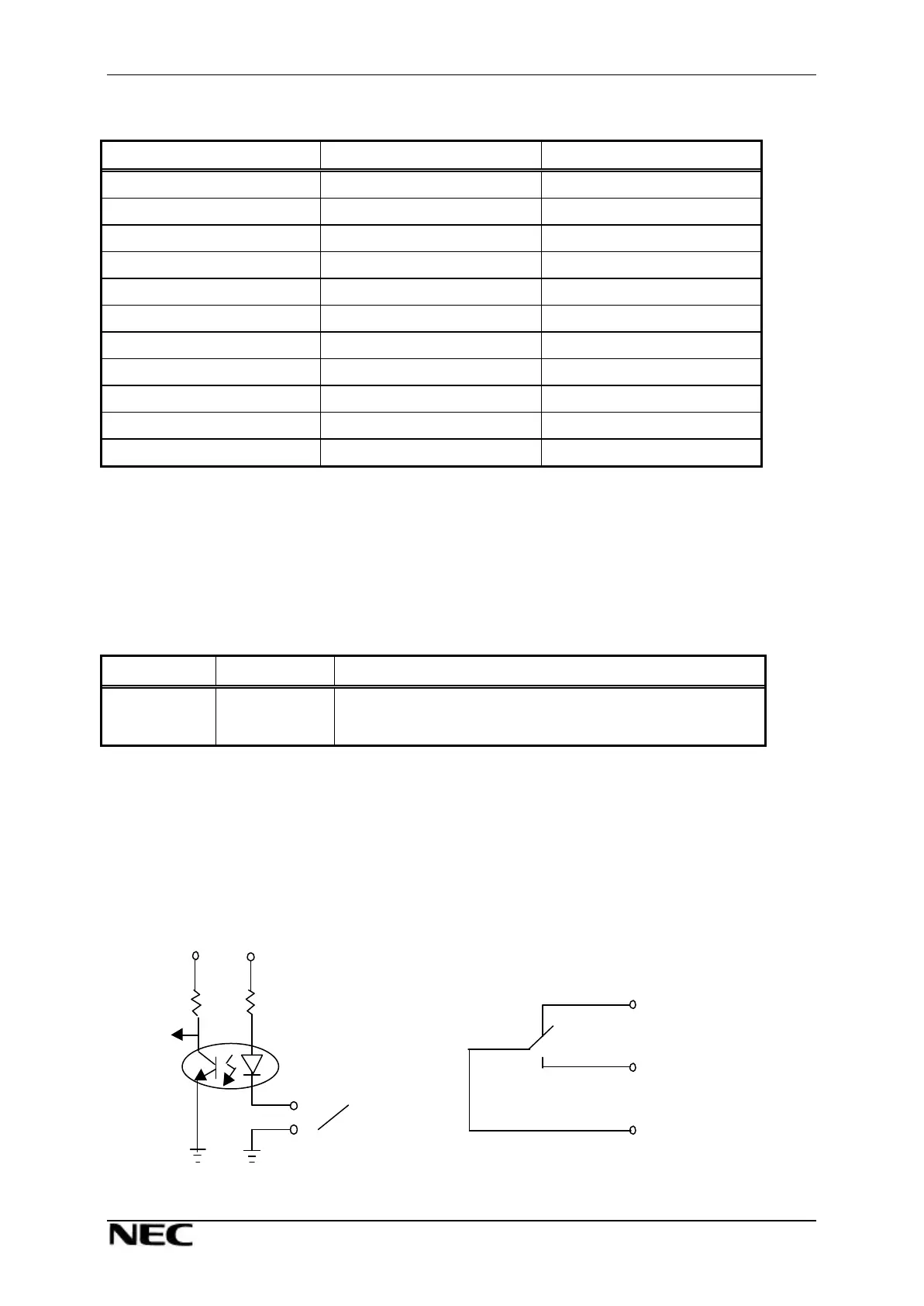
Port condition
DI INPUT Logic : Normal OPEN (
>
200 kohms) DO OUTPUT logic : Controlled from PNMS/T
Event CLOSE (
<
50 ohms) Interface circuit : Relay Form C
Interface circuit : Photo coupler with bias circuit Maximum Current : 0.2 A
OUTPUT Device : Indicates Status on PNMS/T Maximum Voltage : 100 V (AC + DC)
+3.3 V +3.3 V
Close
Event Close
Relay
Event Open
Event Close
COM