Do you have a question about the NEC iPASOLINK EX Advanced and is the answer not in the manual?
Imminent hazardous situation, potentially resulting in death or serious injuries if not avoided.
Caution about entering antenna area during transmission due to high power density.
Use caution when lifting as equipment is heavier than expected.
Use Safety Extra Low Voltage (SELV) for power supply.
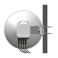
Introduction to the iPASOLINK EX/A and its parts required for setup.
Explains the need for external circuit breakers for power on/off functionality.
Lists the components included in the 1+0 system configuration.
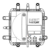
Visual identification of the main iPASOLINK EX/A unit and power injector.
Precautions and guidelines for selecting an appropriate installation site.
Procedures for mounting the iPASOLINK EX/A unit for a 1+0 system.
Summary of the cable installation procedure.
Details the available terminals and their purposes on the iPASOLINK EX/A.
Outlines the procedure for powering on the iPASOLINK EX/A and checking status.
Lists required tools and checks before adjusting the antenna angle.
Steps to set TX power control and adjust equipment angle for optimal signal.
Detailed procedures for adjusting antenna angle for optimal beam alignment.
Safety guidelines and calculation examples for microwave radiation hazard.
| Power Supply | -48 VDC |
|---|---|
| Operating Temperature | -33°C to +55°C |
| Modulation | QPSK |
| Channel Bandwidth | 3.5 MHz |
| Capacity | Up to 1 Gbps |