Door‐PhoneBoxInstallInstructionsandSpecificationsonNECSL1100:
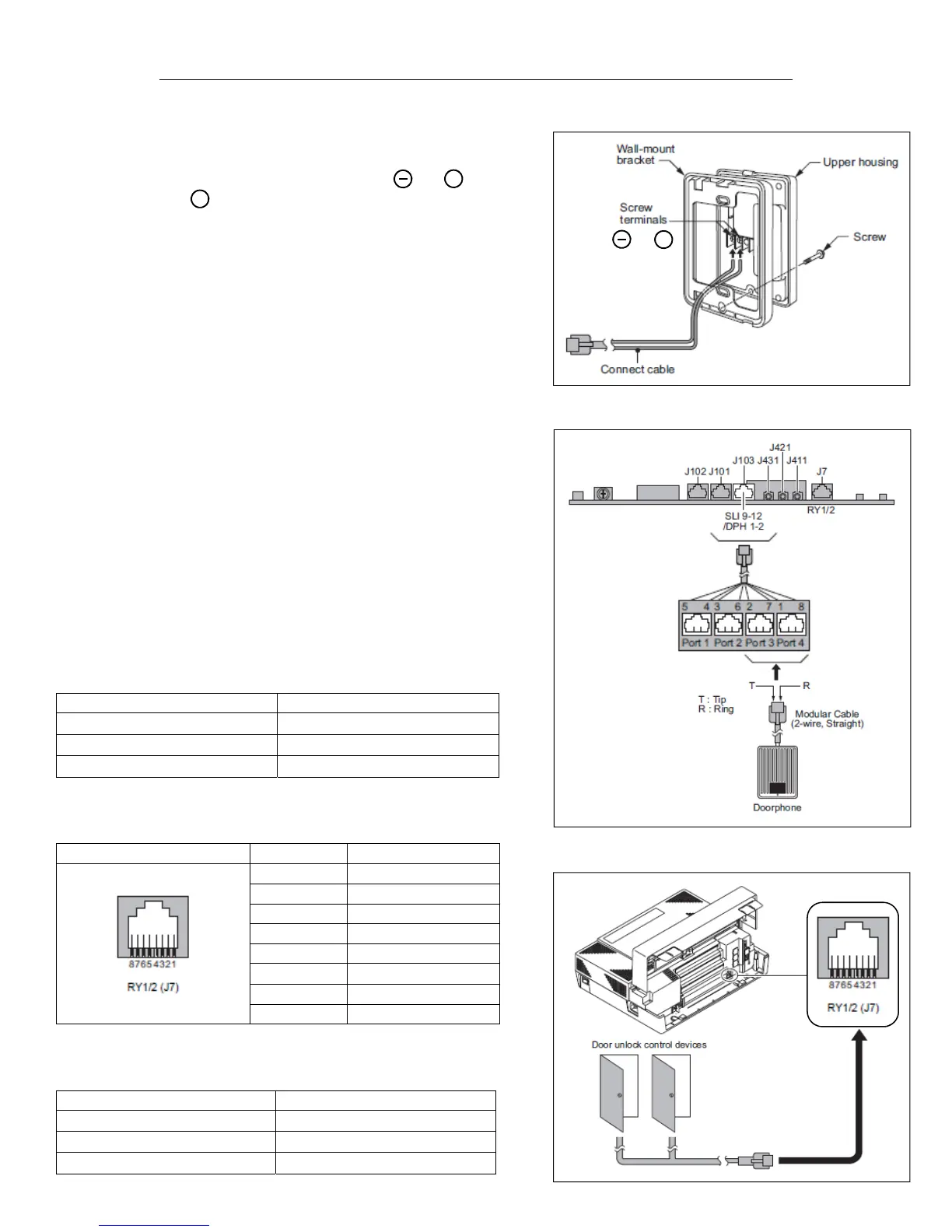
1. RemovethescrewonthefrontoftheDoor‐phoneBox.
2. RemovetheWall‐MountbracketfromtheDoor‐phoneBox.
3. Connectthecabletothescrewterminalsmarkedandonthe
Door‐phonebox.isNOTused.(Notpolaritysensitive)Seefig.1
4. MounttheWall
‐Mountbracketonthewallusingsuppliedscrews.
5. ReplacetheUpperhousingandtightenthescrew.
6. TheDoor‐phoneBoxcanonlyconnecttoAnalogPort3or4onthe
RJ61connectorforanalogextensions.
7. ThereisalimitofTWO(2)Door‐PhoneBoxesper
KSUwithatotalof
SIX(6)betweenthreedifferentKSU’s.
8. BeforeplugginginanyDoor‐PhoneBox,makesureallKSUand/or
ExpansionCabinetsarefullypowereddown.(Thisgoesforall
Multi‐LinePhones,SingleLinePhones,andDSSConsoles)
9. Seefig.2foraconnectionguide.
InstallingtheDoorUnlockDevice(s):
1. AmaximumofTWO(2)DoorUnlockDevicescanbeinstalled
perONE(1)SL1100KSU.
2. Seefig.3foranillustrationofwheretoconnecttheRJ61
ConnectortotheRY1‐2PortontheNECSL1100KSU.
DoorPhone‐BoxSpecificationsforUnlockDevice(s):
ThefollowingchartshowstheDoorPhone‐Boxinterfacespecifications:
Item Specification
OutputImpedance 600 Ω
OutputLevel Nominal250mV(‐10dBm)
MaximumOutput 400mVRMS
ThefollowingchartshowsthepinoutsfortheRJ61CableConnector:
PinNo. Connection
1 Door2
2 Door1
3 Relay2
4 Relay1
5 Relay1
6 Relay2
7 Door1
8 Door2
ThischartshowstheGeneralPurpose/DoorUnlockSpecifications:
Item Specification
RatedVoltage DC48VMaximum
RatedCurrent DC320mAMaximum
Contact NormallyOpen
I
fig.1
I
and
fig.2
fig.3

 Loading...


