9
External relay for load management
Connecting the external relay
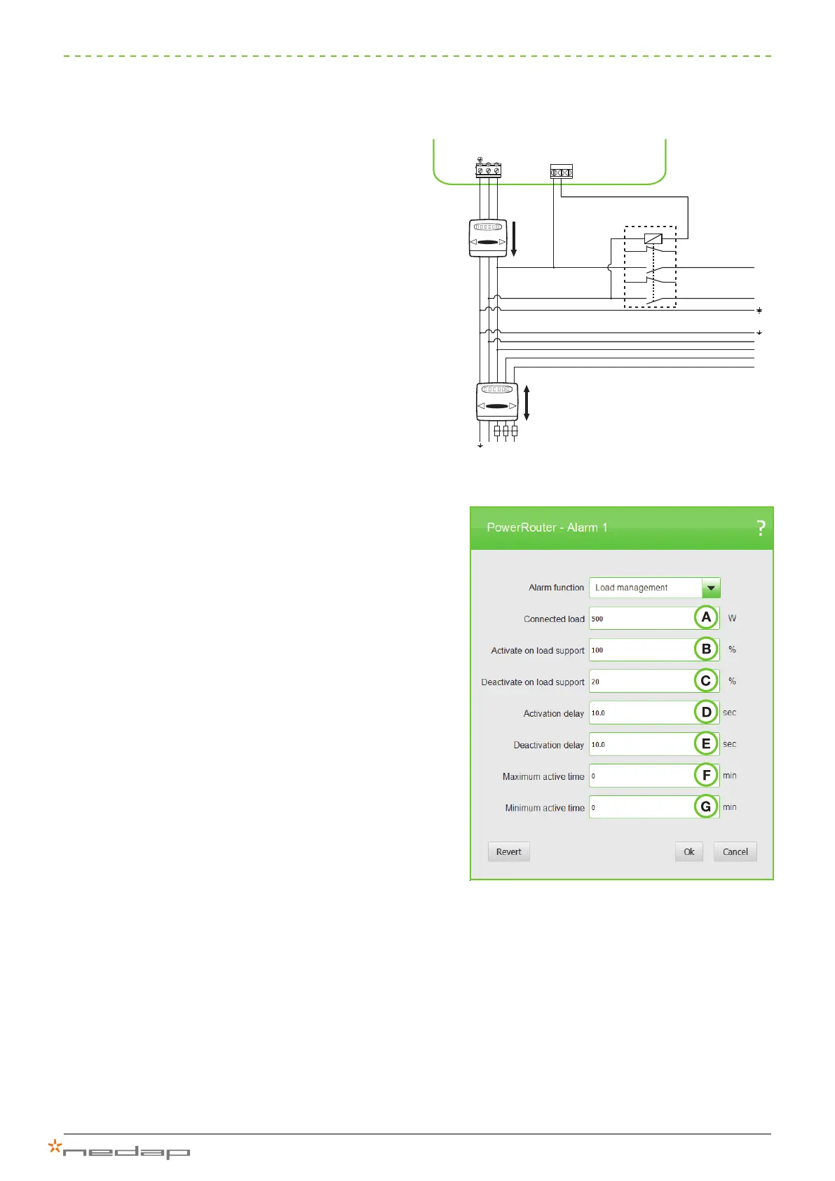
To increase self-use it is possible to have the PowerRouter
automatically connect larger loads when excess solar
energy is available. Below is a circuit diagram which
shows how the external relay (p/n PRA1RLY) is controlled
by one set of potential-free contacts.
Activating load management
Load management is activated using the Software
Installation Tool. This is done by conguring the
parameters as shown below. These values are based
on the capacity being fed into the grid, which means
that this is power above and beyond what is being used
to charge the battery.
A: The capacity of the consumer to be connected when
extra solar energy is available that is not being used
to charge the battery.
B: The percentage of value A that must be available
before the load will be connected. In this example
the extra load will be connected once at least 100%
of 500 W is being fed back into the grid.
C: The percentage of value A at which the load will
be disconnected (can be set at 20-200%). In this
example, the extra load will be disconnected once
the excess power falls below 20% of 500 W.
D: Delay in seconds before the load is switched on,
once the activation conditions have been met (0-100
seconds).
E: Delay in seconds before the load is switched off,
once the deactivation conditions have been met (0-
100 seconds).
F: The maximum time the load will remain connected,
regardless of the available solar power.
G: The minimum time the load will remain connected,
regardless of the available solar power.
Figure 9: Activate load management
Figure 8: Connecting an external relay for load management
0 1 7 7 6 3
0 1 7 7 6 3
AC grid
L3
NCNO
N
L
L2L1N
L3
3 4
R1 R2
L2
L1
L
N
N
5 6
R7 R8
A1 A2
 Loading...