C 25
ELECTRICAL INSTALLATION
7
IMPORTANT!
All electrical work must be done by a qualied electrician ac-
cording to local regulations.
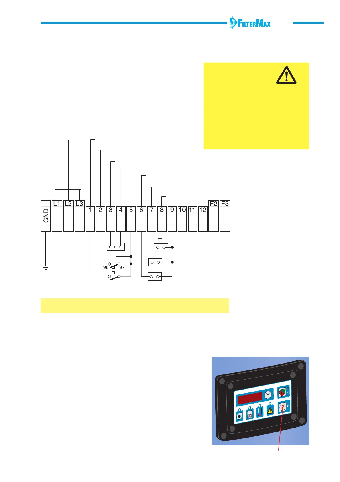
Connect FilterMax C 25 to the mains and connect other compo-
nents and accessories according to wiring diagram on this page.
The accessories must be equipped with a potential free contact.
A lockable safety switch should be tted on the
power supply cable.
P
WARNING!
Risk of personal injury!
• Disconnect the electrical power
before servicing any electrical component.
• All exposed conductive parts of the elec-
trical equipment and the machine shall be
connected to the protective earthing (see
wiring diagram).
• Models with multiple input voltages must
be congured at transformer, motor and
overload.
External START/STOP
Fan motor protector
High dust level
Alarm, 24 V AC
Down time damper (24 V AC)
Fan starter (24 V AC)
Alarm
Damper motor
Fan start equipment
24 V AC, common
Board power, 0 V
Power fuse
Board power, 19 V
Control system fuse
Inputs / outputs
380 V, 60 Hz (Saudi)
400 V, 50 Hz, 3-phase (Europe)
230 V, 50 Hz, 3-phase
(Norwegian)
208 V, 230 V, 460 V, 60 Hz,
3-phase (UL, CSA)
Selecting OFF, nC or nO
Push the 0/1- button and OFF, nC or nO comes up on the display.
OFF The selected input is not activated.
nC Normally closed: The selected input is activated.
nO Normally opened: The selected input is activated.
Select nC or nO depending on type of contact on the connected
accessory. Make a note of the setting which has been selected.
ACTIVATING INPUTS AND OUTPUTS
The inputs or outputs should be activated when accessories
have been connected. Push the P-button to activate actual
input/output. The LED’s indicate, where appropriate, with red
blinking lights.
ACTIVATING THE MENU
Push the P-button and the 0/1-button for more than 4 seconds.
Voltage 208 V 60 Hz 230 V 60 Hz 380 V 60 Hz 400 V 50 Hz 460 V 60 Hz
Current 11 A 10 A 6,4 A 6.1 A 5 A
 Loading...