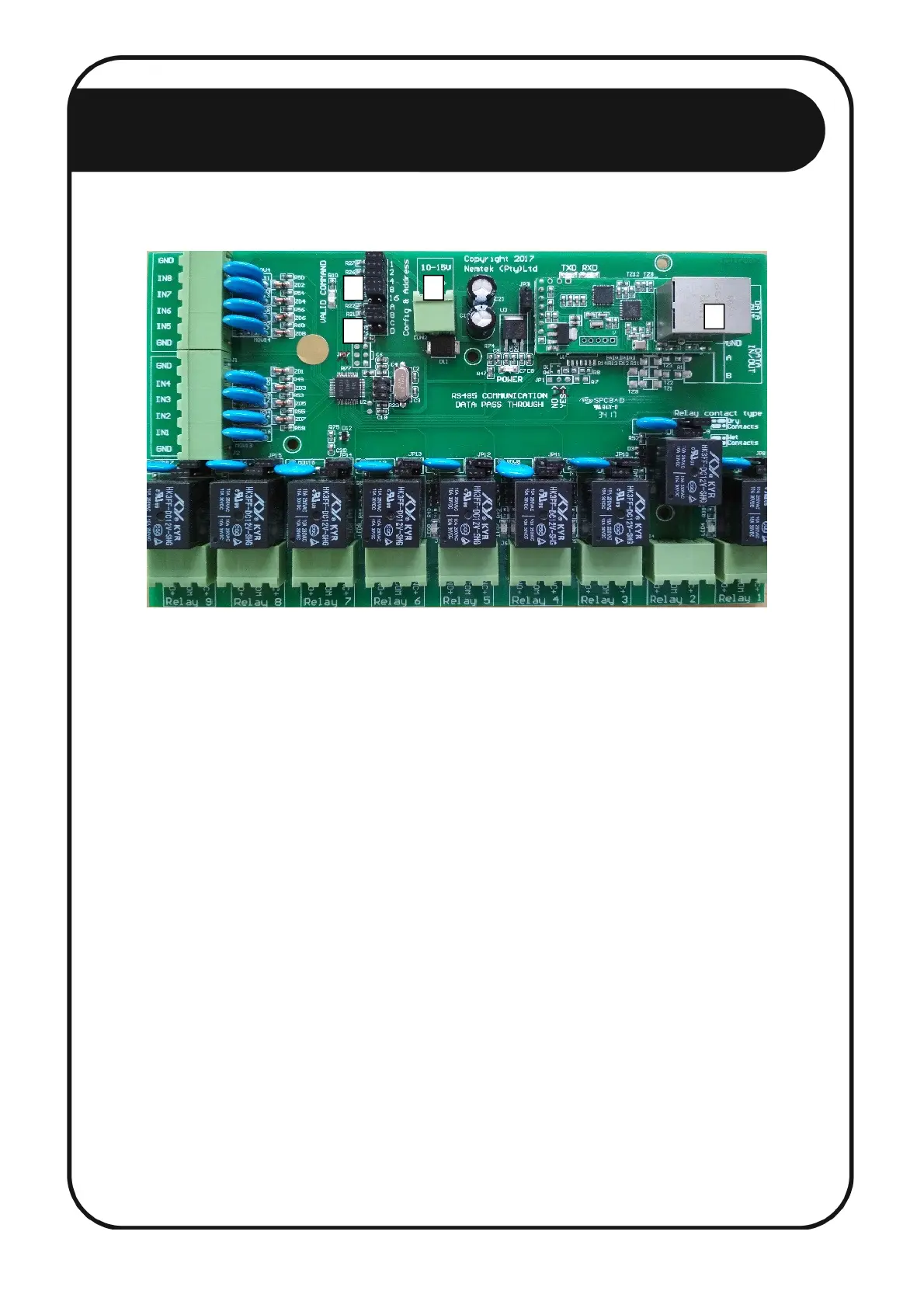
Configuration of the components
1. Disconnect the power connector. [1]
2. Configure the address of the relay board by chronologically using jumpers JP7 1 to 16. When all
jumpers are populated, the address is 1. When a jumper is removed, the corresponding number
will be added to the network address. For example, if jumpers 1, 4 and 8 are removed, the
address will be 1 + 1 + 4 + 8 = 14. The first relay board in the network MUST be configured as
address 1, the second as address 2 etc. Addressing, for example, 3 boards in the network with
addresses 3, 6 and 20 is not allowed, as their addresses must be 1, 2 and 3. This address also
needs to match the address of the 8-way Smart IO Board assigned to the energizer. Relay boards
and energizers are addressed separately from 1 to 32. On the FG7 module, an address offset of 32
is added to all relay boards. Therefore, relay board 1 will be referred to as 33 (1+32), relay board
2 as 34 (2+32) etc. on the FG7. [2]
3. Ensure jumpers JP5 B and C are populated. Jumpers JP5 A and D can either be populated or not.
[3]
4. Connect the relay board to a port on the ethernet switch (the port number does not matter) with
an ethernet cable. [4]
5. Power up the relay board (The NEMTEK Power Pack can be used to power the relay board).
Document Revision History
Revision: 1.0 21 May 2018
THE ETHERNET 8-WAY RELAY BOARD
1
2
3
4
16