Do you have a question about the Neomatica ADM50 and is the answer not in the manual?
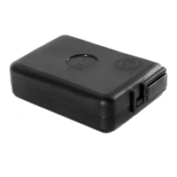
Details the components of the ADM50 terminal, including its modules and buttons.
Explains the basic operation and data transmission of the ADM50 tracker.
Lists technical details for GLONASS/GPS and GSM/GPRS modules.
Details specifications for accelerometer, battery, interfaces, dimensions, and weight.
Describes how to turn the tracker on and off using the power button.
Explains automatic power-on when connecting to a charger or PC.
Details the function to lock or unlock the power button for operation.
Explains the status indications of the green LED for the GLONASS/GPS module.
Details the status indications of the blue LED for the GSM module.
Describes the red LED's indications for the battery charging process.
Explains how to check the battery charge level using the red LED.
Details the configuration and operation of the ADM50 in Beacon Mode.
Explains the configuration and operation of the ADM50 in Tracker Mode.
Describes how the SOS button is triggered and its processing script.
Explains the low battery alert function and its configuration via SMS.
Details the process of updating the tracker's software using a USB connection.
Explains how to update the tracker's software using the GPRS network.
Describes updating software using a firmware file via USB connection.
Provides guidelines for storing and transporting the terminal.
Details the warranty terms, coverage, and exclusions for the device.
Explains the marking on the terminal and its packaging methods.
Outlines the procedures for proper device recycling and disposal.
Lists the items included in the package with the terminal.
The ADM50 is a versatile personal tracker designed for monitoring the location of various mobile or stationary objects, including vehicles, cargo, people, and animals. It integrates a microcontroller, non-volatile memory, GLONASS/GPS and GSM/GPRS modules, an accelerometer, and an alarm button, enabling comprehensive tracking and communication capabilities.
The core function of the ADM50 is to determine its geographical coordinates (latitude, longitude, altitude), exact time (GMT), speed, and direction of movement by receiving signals from GLONASS/GPS satellites. This navigation data is then transmitted to a dedicated server via the GSM/GPRS module, which establishes and maintains TCP/IP connections. The device also supports sending and receiving SMS messages and utilizes GPRS for packet data transmission.
An integrated accelerometer detects vibration levels, which helps manage energy-saving functions automatically. For emergency situations, an "SOS" alarm button is included, which, when activated, sends an SMS message and an information packet with an alarm flag to the server.
Upon activation, the tracker acquires satellite information, determines its location and speed, and establishes a connection to the server. It then periodically transmits accumulated data to the server for further analysis and processing through compatible software on personal computers and other computing devices. If server communication is unavailable, the tracker stores information packets in its non-volatile memory and transmits them once a connection is re-established.
The ADM50 supports two primary operating modes: Beacon Mode and Tracker Mode, allowing it to adapt to different tracking needs, from continuous monitoring to intermittent location updates for extended battery life.
To power on the tracker, press and hold the power button for at least three seconds until all three LEDs illuminate. Release the button, and the blue and green LEDs will turn off, while the red LED will flash to indicate the battery charge level. To power off, press and hold the power button until all three LEDs light up, then turn off after three seconds.
The tracker can be configured to switch on automatically when connected to a charger or a personal computer, regardless of how it was previously turned off (manually or due to a fully discharged battery). This feature is disabled by default and can be configured locally via USB or remotely via GPRS/SMS commands (PENU X, where X=0 for disabled, X=1 for enabled).
A power button lock feature prevents the tracker from being turned off using the power button. While locked, switching on the tracker and checking the battery charge level remain possible. This feature is disabled by default and can be configured locally via USB or remotely via GPRS/SMS commands (POFF X, where X=0 for unlocked, X=1 for locked). To turn off the tracker when this feature is active, the lock must first be disabled.
The ADM50 uses three LEDs (Green, Blue, Red) to indicate its status:
A brief press of the power button will cause the red LED to flash, indicating the battery charge level: three flashes for maximum, two for average, and one for low charge (requiring charging).
The SOS button can be configured to trigger on press or release. When activated, it initiates a script that sends an "ALARM" SMS to up to four pre-listed numbers, determines coordinates, and sends a packet with an alarm flag to the server. The device remains in the SOS processing state until at least one alarm-flagged point is sent. The operating mode of the SOS button (SOSPOL X) and the list of alarm numbers (EventListAdd X, EventListClear, EventListShow) can be managed.
When the battery voltage reaches a set critical level, an SMS message ("battery low!") is sent to authorized phone numbers. This function can be enabled/disabled, and the critical voltage level can be set (BATALARM X,Y).
Firmware upgrades can be performed via two methods:
Important Note on Firmware Updates: It is crucial not to power off the terminal during a firmware upgrade until it is detected by the setting program, as this can damage the software, requiring manufacturer intervention for recovery.
Terminals should be stored in a warehouse at temperatures between +5 °C and +40 °C with relative humidity not exceeding 85%. After transportation in sub-zero temperatures, devices should be kept at room temperature for 24 hours before use.
The manufacturer provides a 12-month warranty (6 months for the built-in battery) from the date of sale, provided the consumer adheres to all transportation, storage, installation, and handling rules. The warranty does not cover mechanical damages, signs of oxidation or liquid penetration, absence of housing, repairs performed outside authorized service centers, electrical or other damages from unacceptable external power network changes or improper use, or disabling due to unauthorized software upgrades. The device software is licensed, and terms of limited liability are available on the manufacturer's website.
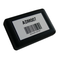
Marking is present on the terminal housing. Devices are packed in individual boxes for protection during transportation and storage, with multipack options available.
Device recycling must be performed in accordance with national and local norms and requirements.
| Model | ADM50 |
|---|---|
| Brand | Neomatica |
| Update Rate | Up to 10 Hz |
| Accuracy (Position) | 2.5 m CEP |
| Accuracy (Velocity) | 0.1 m/s |
| Time to First Fix (Cold Start) | 26 s |
| Time to First Fix (Hot Start) | 1 s |
| Sensitivity (Tracking) | -167 dBm |
| Sensitivity (Acquisition) | -148 dBm |
| Interfaces | RS-232, USB |
| Operating Temperature | -40°C to +85°C |
| Category | GPS |
| Protocols | NMEA, UBX |
| Channels | 72 channels |