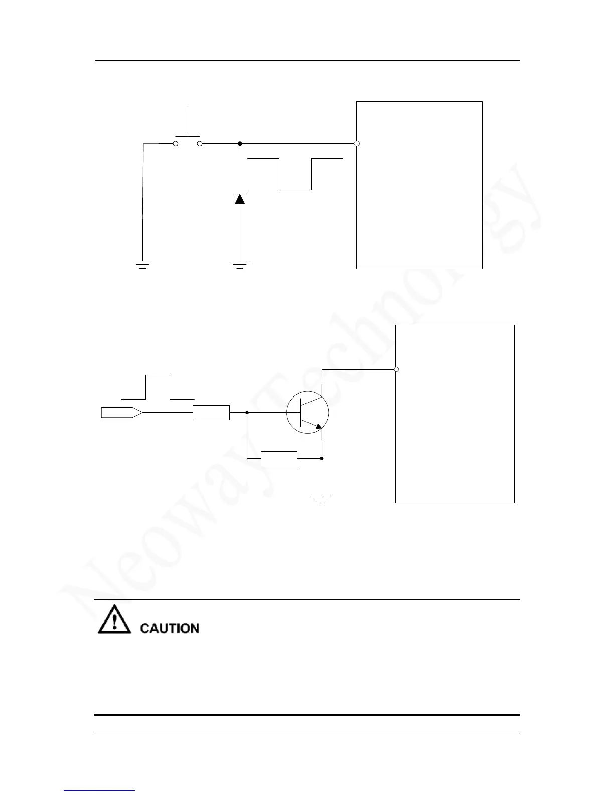
Figure 3-8 Reference circuit for power-on/off control
Figure 3-9 Reference circuit for power-on/off controlled by high level
In Figure 3-9, high level takes effect for ON/OFF on the user side (USER_ON) after level shifting.
R1 and R2 can be adjusted according to the driving capability of the USER_ON pin.
Use a common NPN transistor, e.g. MMBT3904; or a digital NPN transistor, e.g. DTC123.If digital
transistor is used, delete R1 and R2.
l
Level abnormalities at interfaces connected to the external MCU, especially the UART port, might
affect the power-on procedure of the module. For example, when a module is turned on, the IO ports
of the MCU are still in output status because they have not been initialized completely. The module
might fails to start if the UTXD signal (output pin) is forced to pull up or down.
l
The better way to rescue the module from abnormal condition, is to apply a power OFF-ON procedure,
rather than using the ON/OFF control signal. In fact ON/OFF signal is software-dependent.
GPRS Module
ON/OFF
TVS
S 1
USER_ON
GPRS Module
ON/OFF
4.7K
47K
R1
R2