Networkable VAV Controller
Specification and Installation Instructions
www.neptronic.com EVCB Standard Page | 6
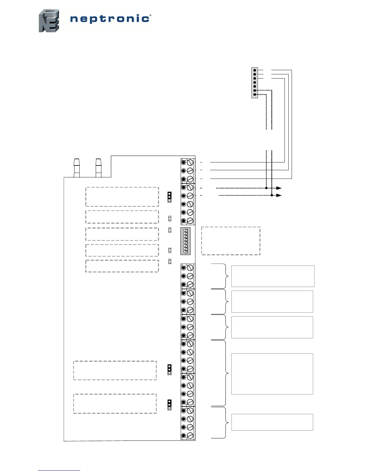
Wiring
We strongly recommend that all Neptronic products be wired to a separate grounded transformer and that transformer shall service
only Neptronic products. This precaution will prevent interference with, and/or possible damage to incompatible equipment.
DS1 DIP Switch
The 8 DIP switches
represent a binary logic to
calculate the MAC address .
Default = all OFF
TB1 TB3TB2 TB4 TB5 TB6
Power
Status
ON
1 2 3 4 5 6 7 8
DS1
INT EXT
TB7
JP2
INT EXT
JP1
3 2 1
AI2
AI1
COM
2 analog inputs (config.)
External temp , changeover , normally cool/
heat, setpoint air flow , CO2, air supply temp
3 2 1
AO2
AO1
COM
2 analog outputs (config.)
Cool ramp 1 or 2, heat ramp 1 or 2, CO2,
setpoint airflow
3 2 1
DI2
DI1
COM
2 digital inputs (config.)
DI2: Override, normally cool/heat
DI1: OCC open /close, NSB open /close
3 2 1
COM
24Vac input
(TO2/TO1)
TO1
4
TO2
7 6 5
COM
24Vac input
(TO3/TO4)
TO3
8
TO4
4 TRIAC outputs (config.)
Cool 1 or 2, heat 1 or 2, CO2
On/Off (config close/open percent)
Floating (config float time)
Pulse (heat only)
Direct or reverse
3 2 1
24Vac
COM
4
24Vac
COM
Power Input/Output
24Vac
3 2 1
COM
A+ (in)
B- (in)
To other
BACnet
devices
High
Total Pressure
Low
Static Pressure
TXD
RX D
JP3 EOL
JP2 (TO3 / TO4 input voltage)
INT = 24Vac supplied internally by TB1
EXT = Apply 24Vac to pin 5 of TB2
JP1 (TO1 / TO2 input voltage)
INT = 24Vac supplied internally by TB1
EXT = Apply 24Vac to pin 1 of TB2
TB1
1
2
3
4
5
6
7
3 2 1
Data
COM
Pwr
Data
Pwr
COM
Optional:
connect
to enable
service port
5 4
A+ (out )
B- (out )
JP3 (End of line)
None = No end of line
120 Ohms = Last node on network
TXD Flash
transmitting data via network
RXD Flash
receiving data via network
Power On
24Vac applied to TB1
Status Flash
communicating via thermostat
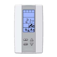
TRL24 and TDU