14 Evolution Series - XPAND NGP\00329 Rev. C 23-06-2006
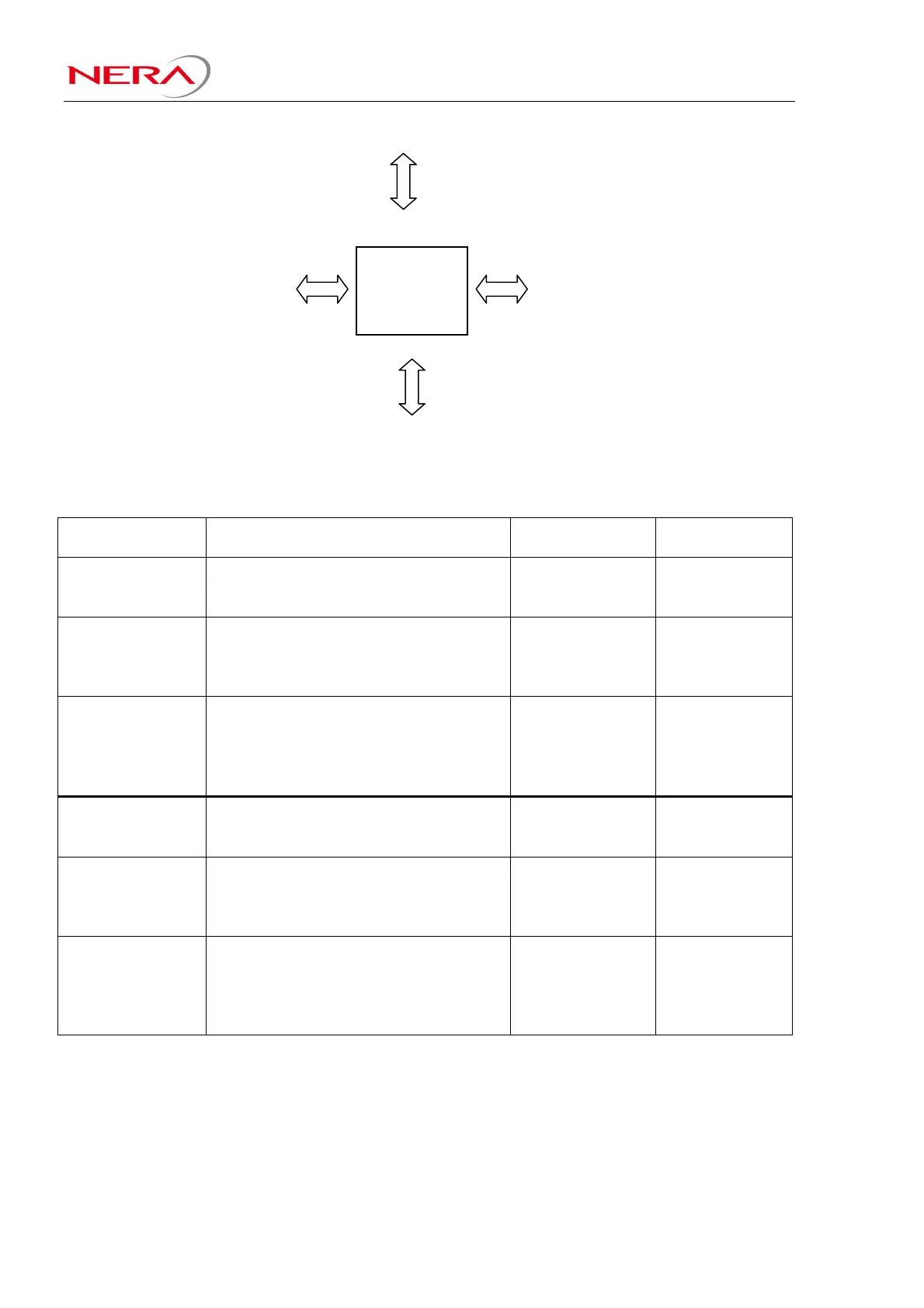
Figure 2-2: PDH X-Connect
Configuration examples:
Terminal
Configuration:
Units and location in IFU: PXC-port to be
used:
Comment:
100Mbps FE
+ 25E1, 1+0
(one IFU)
1 x RIU in IFU slot 5
1 x 25E1 Line interface in IFU slot 3
SU-FE in IFU slot 1
3
1
0
PXC-port 2 not
used
100Mbps FE
+1-25E1, HSB
(one IFU)
1 x RIU in IFU slot 5
1 x RIU in IFU slot 4
SU-FE in IFU slot 1
1 x 25E1 Line Interface in IFU slot 3
3
3
0
1
PXC-port 2 not
used. In HSB is
traffic switched
after the PXC
50Mbps FE
+26-50E1, HSB
(one IFUs)
1 x RIU in IFU slot 5
1 x RIU in IFU slot 4
SU-FE in IFU slot 1
25E1 Line Interface in IFU slot 3
25E1 Line Interface in IFU slot 2
3
3
0
1
2
All PXC-ports
used.
100Mbps FE
+ 16T1, 1+0
(one IFU)
1 x RIU in IFU slot 5
1 x 16T1 Line interface in IFU slot 3
SU-FE in IFU slot 1
3
1
0
PXC-port 2 not
used
100Mbps FE
+1-16T1, HSB
(one IFU)
1 x RIU in IFU slot 5
1 x RIU in IFU slot 4
SU-FE in IFU slot 1
1 x 16T1 Line Interface in IFU slot 3
3
3
0
1
PXC-port 2 not
used. In HSB is
traffic switched
after the PXC
50Mbps FE
+17-32T1, HSB
(one IFUs)
1 x RIU in IFU slot 5
1 x RIU in IFU slot 4
SU-FE in IFU slot 1
16T1 Line Interface in IFU slot 3
16T1 Line Interface in IFU slot 2
3
3
0
1
2
All PXC-ports
used.
PDH
X-Connect