24 Evolution Series - XPAND NGP\00329 Rev. C 23-06-2006
4.2. General Equipment Specifications
4.2.1. Equipment Reference Points
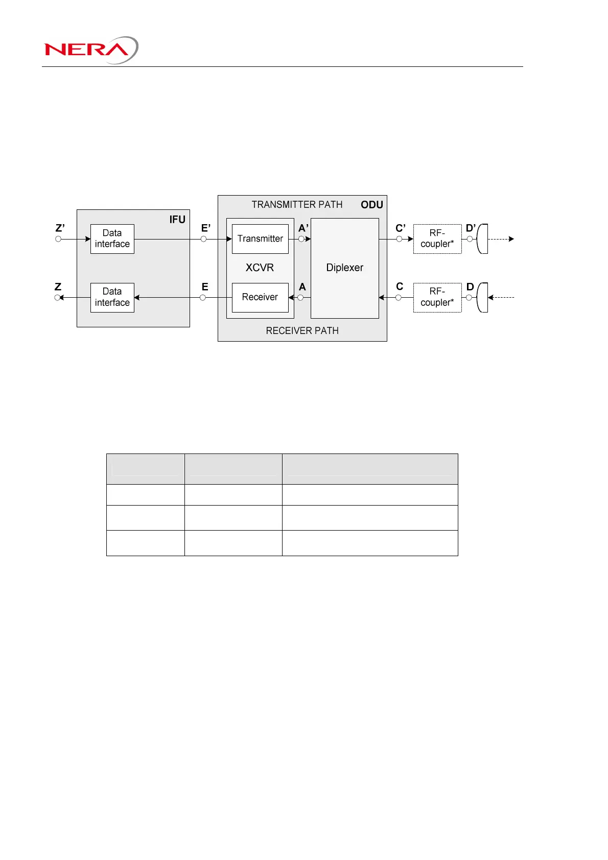
A principle block diagram for a digital radio relay system, including the main blocks, is shown in Figure
4-1. The block diagram includes marked interface points, which serve as reference points for several
technical parameters used in this document.
* The RF-Coupler is used in HSB and 1+1/2+0 single polarised configurations
Figure 4-1 Principle block diagram for a radio system
4.2.2. ETSI Equipment Class
The equipment is compliant to the relevant specifications in EN 302 217 for the following classes.
BW Modulation Class
7 MHz QPSK 2
14 MHz 16 state 2 and 4
28 MHz 32 state / 128 state 4, 5A and 5B
Table 4-3 ETSI Equipment Class
4.2.3. Electromagnetic Compatibility Conditions (EMC)
ETSI: The equipment conforms to the EMC standard as specified in EN 301 489 part 1 and 4.
FCC: The equipment conforms to FCC Part 15 subpart B class A.
4.2.4. Safety conditions
The equipment conforms to EN 60215, EN 60950 and UL/CSA 60950. The optical interfaces conform to
EN 60825-1 and EN 60825-2.
4.2.5. RoHS and WEEE compliance
The equipment is compliant to EU Directive 2002/95/EC (RoHS) and EU Directive 2002/96/EC (WEEE)
4.2.6. Equipment Type Approval
The equipment is type approved and labelled according to EU Directive 1999/5/EC.
The CE marking is located on both IFU and ODU.