NGP\00329 Rev. C 23-06-2006 Evolution Series - XPAND 33
5.5. Diplexer and Antenna Interface
5.5.1. General description
The diplexer determines the ODU sub-band coverage and duplex spacing. Most frequency bands are
divided into only two sub-bands. See APPENDIX 1 for details. ODU transmit and receive frequency can
be set to any frequency within the given pass-band range.
5.5.2. RF-Coupler
The additional loss for RF-Coupler is given in Table 5-16. The RF-Coupler is used in protected
configurations and single polarised 2+0 systems.
Asymmetrical RF-Coupler
Symmetrical RF-
Coupler
Main Protection
Nom Max Nom Max Nom Max
Transmission loss [dB]
Tx or Rx
3.4 3.8 1.5 2 6.5 7
Table 5-16 RF-Coupler loss
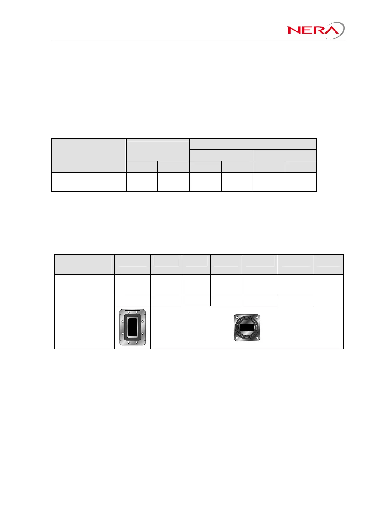
5.5.3. Interface to Antenna feeder system – non integrated antennas
The interface between the ODU-Diplexer (1+0 configuration) or HSB-coupler (HSB configuration) and
the antenna feeder system is rectangular waveguide. The ODU-Diplexer and HSB-coupler flange types
and corresponding waveguides to be used (if remote mount) is shown in Table 5-17. The ODU-Diplexer
and HSB-coupler aluminium flanges are protected by chromate coating.
Frequency band
[GHz]
L6/U6 7/8 11 13 15 18/23/26 32/38
Waveguide
(remote mount)
R70 /
WR137
R84 /
WR112
R100 /
WR90
R120 /
WR75
R140 /
WR62
R220 /
WR42
R320 /
WR28
PDR70 CBR84 CBR100 CBR120 CBR140 CBR220 CBR320
ODU-Diplexer and
HSB-Coupler
Flange types
Table 5-17 ODU flanges and waveguide