2-73
87519804 NA Issued 11-06 Bur
CHAPTER 2 - 667TA ENGINE OVERHAUL
ENGINE REPAIR MANUAL
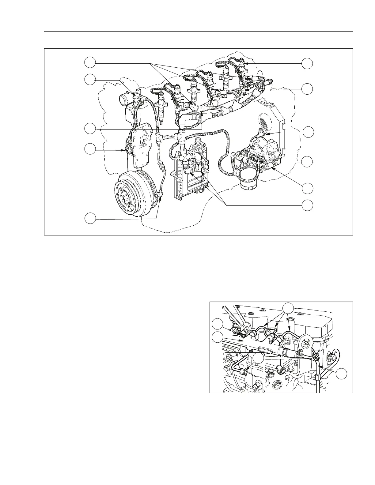
STEP 6
BS06K225
Figure 2-98
Disconnect the engine cable by disconnecting the
following connectors:
• Connectors (1) from injector wiring (6)
• Engine coolant temperature sensor on the
thermostat (2)
• Common rail fuel pressure sensor (3)
• Crankshaft speed sensor (5)
• Boost pressure / temperature sensor (7)
• Camshaft sensor (8)
• High pressure regulator (10)
• EDC7UC31 control unit (11)
STEP 7
BS06K226
Figure 2-99
Disconnect from the common rail (2):
• Fuel line (4) according to procedure on step 3
page 2-72
• Fuel lines (5)
• Injector manifolds (3)
• Remove the bolts (1) and disconnect the common
rail (2)
1. INJECTOR CONNECTIONS 5. CRANKSHAFT SPEED SENSOR
9. FUEL HEATER- TEMPERATURE
SENSOR
2. ENGINE COOLANT TEMPERATURE SENSOR 6. INJECTOR 10. HIGH PRESSURE REGULATOR
3. COMMON RAIL FUEL PRESSURE SENSOR
7. BOOST TEMPERATURE-PRESSURE
SENSOR
11. EDC7UC31 CONTROL UNIT
4. OIL TEMPERATURE- PRESSURE SENSOR 8. CAMSHAFT SENSOR
9
4
3
2
10
1
11
8
6
7
5
1
2
3
4
5
 Loading...