9
Figure 5 — IPV Leveling Valve
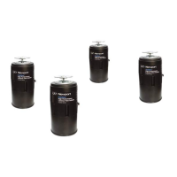
Figure 6 — Valves attaching to isolator
The valves should be attached to the isolators as shown in Figure 6 after
installing the table top.
1. Set the table height adjustment screw on each valve to the center of its
travel (Figure 6).
2. Attach the leveling valve to the isolators as shown in Figure 6. Secure
the valve to the bracket using the two mounting screws and the nutplate.
Control arm
Table height sensor
Metering
needle valve
Isolator pressure
gauge
Table height
ad
ustment screw
Air supply
Air line to isolator
Mounting screw holes
Over-pressure relief valve
Table height
ad
ustment screw
 Loading...