RollMaster™5000
ALWAYSwearsafetygogglesorprotectiveeye‐wearwhenoperatingtheunit!
1700JasperSt.,UnitF,Aurora,CO80011T800.624.6706F303.364.7796•Newstripe.com
RollMaster™5000Manual/3068.1116
Page3
ASSEMBLY
1.UnpacktheRollMaster™5000chassisassembly,rollercarrier,handles,pail,andpartsbags. The
majorcomponentsareheldtogether with¼”diameterboltsin¾”length,and5/16”diameterbolts
in1‐1/2”lengthswithlockingnutsandwashers.
2.Placethewheelsofthechassisonaflatsurface. Laythehandleassemblybehindtheunit(pail
holderside)withthegripspointingdownandthebottomofthehandlestowardstheunit.
3.Mountbottomendofhandleassemblyonchassis(handlesfitonoutsideofframe)with
5/16"x1‐1/2"boltswithwashersfromtheinsideoutthroughthemountingholesinchassis
andhandleswithlockingnutsontheoutside.(Therearenowashersontheoutside)Donot
tightencompletely.
4.Swinghandlesintoposition.Alignupperholesinhandlesupportbraces(bracesontheoutsideof
handles)withholesinhandleandinsert5/16”x1‐1/2”longcarriageboltsinholesfromthe
outside.Tightenwithlockingnutsontheinside.Nowtightenalloftheabovehandle‐mounting
bolts.Routethetriggerwiringharnessbetweentherearaxleandchassistowardsthebattery
cover.Pushtheendsoftheharnessupthroughthegrommetinthechassisintothebatteryarea.
5.Removethefourbolts&washerssecuringbatterycover.Slidecoverupwardsandsetaside.
6.Removethetwowingnutsthatsecurethebatteryholddownplate.Removetheplate.Slide
anewbatteryonthechassisbetweenthebatteryholddownboltsandpositionthebattery
withterminalstotherearofthemachine.Installthebatteryholddownplateandsecurewith
wingnuts
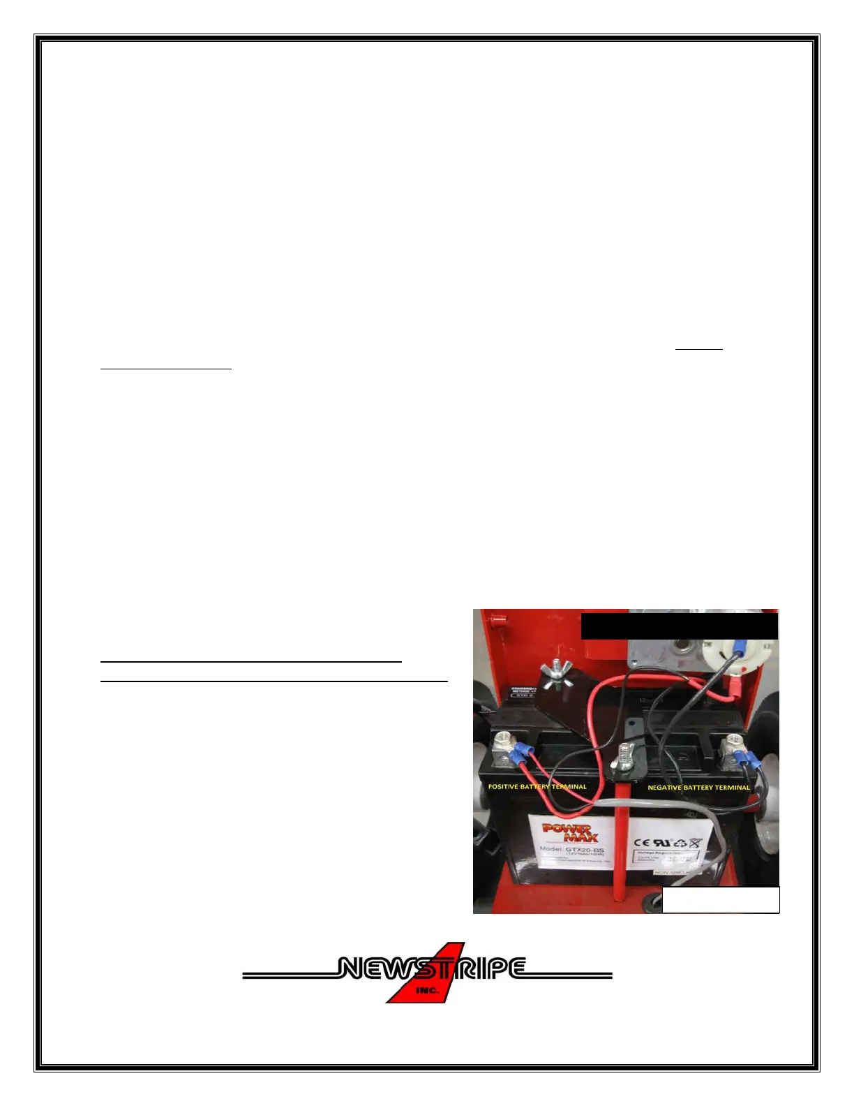
Installthepositivesidefirstwheninstalling
connections.PicturesforwiringareshowninPic2.
7.Attachtheredwireleadfromthepainttrigger
harnessandtheredwireleadfromthebattery
chargertothetopofthepositiveterminalsideof
thebattery.
8.Attachtheblackwirelead(withredtapemarker)
fromthepainttriggerharnesstothebottompostof
thepumpmotor.(Markedwithareddot)
9.Attachthetwoblackwireleads(fromthepump
motorandthebatterychargerthataretied
together)tothetopofthenegativeterminalsideofthebattery.
BATTERYNOTINCULDED
Pi
2
 Loading...