Physical Description
User Manual forAZ710 Up Converter
version 1.2
4
SHAPING THE FUTURE OF SATELLITE COMMUNICATIONS
Press the digit keys 0 up to 9 to enter numerical values. When there is a need for
hexadecimal characters, press 0 – 9 to represent values zero to nine and A
through F to represent values ten to fifteen. To enter characters, press 0 – 9
multiple times until the desired character appears. Characters will appear first,
numbers last.
3.1.3 LEDs
There are six LEDs on the front panel.
Figure 3 -SDH Converter LEDs
Data In: green At least 1 data input is active and valid
Data Process: green The data are processed prior to transmission
Tx on: green The transmit is on
Act. Alm: red The actual alarm(s) is/are present
Mem. Alm: red The memorised alarm(s) is/are present
Test: orange On when the device is in test mode
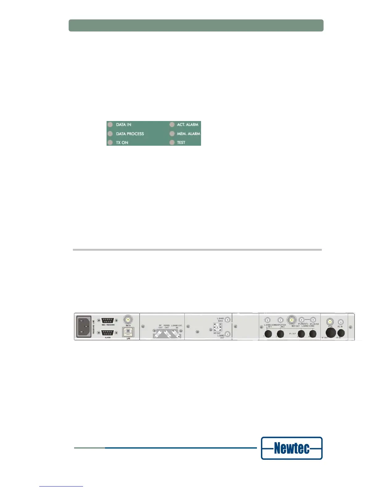
3.2 Back Panel Description
The figure below shows the possible connections on the Up Converter. Keep in
mind that the back panel connections available on your device depend on your
specific hardware configuration. Therefore, they may differ from the ones shown in
the figure below. The back panel consists of several hardware modules. In the
following paragraphs these modules are described in more detail.
Figure 4 – Back Panel of the AZ710