TECHNICAL DATA
Power source
DC 2 x 1.5V AA battery
Battery: Gold Peak Group: GP 15A LR6 or Energizer: E91
Radio frequency
433 MHz
Range, clear line of sight
up to 20 m
Alarm signal
85 dB (A) at 3 metres
Operating temperature
5°C – 45°C
Ambient humidity
10 – 90 %
Temperature sensors
54-70 °C (EN-54)
This instruction folder contains important information
on correct installation and maintenance of your smoke
alarm. Read through the whole folder before installing
it, and keep the folder for future reference.
Nexa’s FS-588/RF smoke alarm is designed to detect
smoke particles. It has a built-in temperature sensor to
provide an early warning in the event of a fire (as long
as it is positioned and maintained correctly).
Primary features:
• Built-in temperature warning device
• High levels of sensitivity and stability
• Test and pause functions
• LED shows normal function
• Signal on low battery voltage
• Can be connected in series with up to 12 smoke alarms
IMPORTANT
• The radio range may vary depending on the location, the
design of the building and the materials used in the building.
• Do not remove or disconnect the batteries to stop false
alarms as this will disable the vital function of the smoke
alarm. Open windows or ventilate the air around the smoke
alarm in order to stop it, and/or press the pause button.
• The smoke alarm is intended for use for use in single-
family homes. In multiple-occupancy buildings, each
home must be equipped with its own smoke alarms.
• This smoke alarm is not suitable for use in buildings that
are not used for residential purposes. The smoke alarm
is no substitute for a full alarm system that is required
by law or by the fire authorities.
• The smoke alarm detects combustion particles in the air
(smoke). It does not react to flames or gas.
• The smoke alarm is designed to emit an alarm signal if a
fire is developing.
• The smoke alarm should be tested every week and
replaced every ten years.
POSITIONING THE SMOKE ALARM
For the smoke alarm to provide an early warning, it has to
be installed in the location where the re starts. Therefore,
Nexa recommends that you install smoke alarms in each
room and on all oors.
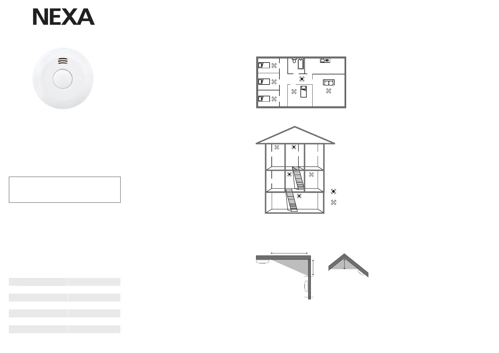
Single-level home: To achieve minimum protection,
position the alarm in the entrance hall between the living
areas (including the kitchen) and the sleeping areas.
Position it as close as possible to the living areas, and
make sure the alarm can be heard by anyone in the
bedrooms. See Figure 1, for example:
Multi-storey home: To achieve minimum protection,
position and alarm in the stairwell (at ground level) and
another alarm above the landing on the top oor, as well
as an alarm on the ceiling in the basement at the foot of
the stairs. This covers the basement level, but not crawl
spaces and unfurnished attics.
See the example in Figure 2.
Ceiling installation
Hot smoke rises and spreads, so installing your smoke alarm in
a central location on the ceiling is recommended. Avoid areas
where air does not circulate, e.g. corners. Also keep it away
from objects that may prevent the free ow of air. Position the
device at least 30 cm from light ttings or interior ttings that
may prevent smoke/heat reaching the detector. Position it at
least 1 metre away from the wall.
See Figure 3A.
Wall mounting, if ceiling mounting is not possible
Avoid installing the device a long way into a corner.
Position the upper edge of the smoke alarm at least 15 cm and
no more than 30 cm away from the ceiling. See Figure 3A.
Sloping ceilings
In the case of sloping surfaces or ceilings that move up
towards a ridge, the detector must be installed 90 cm from
the highest point, measured horizontally, because still air
under the ridge may prevent smoke reaching the device.
See Figure 3B.
NOTE: There must be an alarm in every room (except the
kitchen, bathroom and garage) to provide recommended/
maximum protection. DO NOT POSITION AN ALARM IN THE
KITCHEN or BATHROOM as cooking smells or steam may
activate the alarm. DO NOT POSITION AN ALARM IN THE
GARAGE as there is a risk of it being triggered by exhaust fumes.
INSTALLATION
1. Remove the mounting plate on the back of the
smoke alarm by rotating the mounting plate
counterclockwise.
2. Insert 2 x AA / LR6 batteries. Make sure you are using
the correct polarity (+/-).
3. Test and programme the smoke alarm – see the
sections TESTING and PROGRAMMING.
4. Install the mounting plate in a selected location on the
ceiling. Take care when positioning your smoke alarm.
5. Place the smoke alarm on the mounting plate and rotate
the smoke alarm clockwise until it clicks into place.
6. Press the test button to check that smoke alarm is
working correctly.
TESTING
Test your smoke alarms by pressing the test button. Your
smoke alarm will respond by emitting an alarm signal.
• Test your alarms both before and after installation so
as to be sure that they are working.
• Only test your alarms using the test button. Never use
a naked ame as this may destroy the smoke alarm.
• Get into the habit of testing your smoke alarms once a week.
Testing interlinked alarms: It takes up to 60 seconds
for all interlinked alarms to respond/emit an alarm.
HOLD DOWN THE TEST BUTTON until all smoke
alarms have emitted an alarm.
PROGRAMMING
The FS-558 / RF is equipped with RF transmitter
and receiver to communicate with each other. For
this to work, the re alarms must be connected by
programming.
Select one of the smoke alarms as the master unit and
mark it with an M for ease of recognition.
During programming, the master device sends out radio
code to the other smoke alarms to interconnect them.
1. Press the master unit test button for about 15
seconds until the LED indicator lights up with a solid
light. The master unit is now in programming mode
and ready to hand out radio code the other smoke
alarms. The master unit stays in programming mode
for about 30 seconds before returning to normal
mode.
2. With the master unit in programming mode, press
and hold the slave unit’s test button until the LED
indicator is solidly lit (1-3 seconds), release the
button. Both the master unit and slave unit LED
indicators will now blink quickly for 2 seconds. This
shows that the two are interconnected.
3. Repeat step 2 with all slave units to be connected to
the same system.
4. Quit programming by pressing the test button on the
master unit so that the LED indicator goes out.
HALL-
WAY
BASEMENT
LIVING ROOM
BATHROOM
KITCHEN
BEDROOM
BEDROOM
BEDROOM
BEDROOM
HALLWAY
Maximum /
recommended
protection
Minimum
protection
CEILING
WALL
BEST IN THE
MIDDLE OF THE ROOM
Min. 1 m
Min.
15 cm
Max.
30 cm
BATHROOM
BEDROOM
LIVING
ROOM
LANDING
KITCHEN
HALL-
WAY
BASEMENT
LIVING ROOM
BATHROOM
KITCHEN
BEDROOM
BEDROOM
BEDROOM
BEDROOM
HALLWAY
Maximum /
recommended
protection
Minimum
protection
CEILING
WALL
BEST IN THE
MIDDLE OF THE ROOM
Min. 1 m
Min.
15 cm
Max.
30 cm
90 cm
LIVING
ROOM
LANDING
KITCHEN
FIGURE 1. Single-level home
FIGURE 3A FIGURE 3B
FIGURE 2. Multi-storey home
LOCATION ON CEILING AND WALL
OPTICAL SMOKE ALARM FOR
WIRELESS CONNECTION IN SERIES
Model: FS-558/RF
 Loading...