Do you have a question about the Nexans Euromold K480TB/G and is the answer not in the manual?
Warning regarding changed installation procedures for the cable reducer.
Verify cable core insulation diameter against the reducer range in the provided table.
Lists all components required for the successful installation of the connector assembly.
Position cable into bushing, mark center line, and strip outer sheath to specified length.
Prepare screen wires for indoor or outdoor applications, including mastic and tape application.
Cut the cable to the specified length from the outer sheath edge.
Remove the semi-conductive screen to a specified point, distinguishing between extruded and bonded types.
Remove core insulation for compression (TBC-X) or mechanical (TMBC-X) contacts to a specific depth.
Slightly bevel the core insulation edge and thoroughly clean the conductor and screen wires.
Lubricate specified areas and slide the cable reducer down the cable until flush with the tape marker.
Remove the protective adhesive tape from the conductor after reducer installation.
Install the rod, lubricate specified areas, and slide the reducer onto the rod.
Slide the reducer down the cable, remove the rod and protective tape for completion.
Wire brush conductor, fit contact, and position it correctly aligning the contact hole with the bushing.
Check and crimp the contact, verifying distance 'Z' before and after crimping.
Adjust reducer position if needed, remove burrs, and wipe off excess inhibitor.
Wire brush conductor, insert centre ring as per instructions, and position contact.
Tighten the contact and verify distance 'Z' is within the specified range.
Clean, lubricate, and slide the connector housing onto the cable, ensuring proper alignment and reducer position.
Clean and lubricate the connector and bushing interfaces, then push the connector onto the bushing.
Insert the clamping screw and tighten it to 50 Nm using a torque wrench.
Install the insulating plug and tighten it to 30 Nm using a torque wrench.
Install the cap on the BIPR insulating plug, using a vent rod and ensuring firm positioning.
Install the cap on the BIPA insulating plug, using a vent rod and securing the locking point.
Bend screen wires into a pig tail and connect the earthing lead to the system earth.
Clamp the cable close to the connector to support its weight and prevent strain.
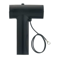
The document describes the installation instructions for the separable tee connector, type C interface, specifically the EUROMOLD® (K)480TB/G, designed for use up to 24 kV. This connector is intended for copper wire screened cables with an extruded semi-conductive screen and conductors made of copper or aluminum.
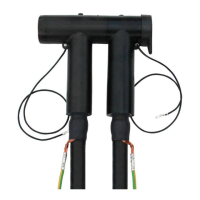
The (K)480TB/G separable tee connector serves as a crucial component in high-voltage electrical systems, enabling a secure and reliable connection between a cable and equipment bushing, or between two cables in a tee configuration. Its primary function is to provide electrical insulation and mechanical protection for the connection point, ensuring safe operation within the specified voltage range. The connector facilitates the termination of cables to switchgear, transformers, or other apparatus equipped with a type C interface. The design incorporates a cable reducer to accommodate various cable core insulation diameters, ensuring a snug fit and proper sealing. The installation process involves careful preparation of the cable, including stripping the outer sheath and semi-conductive screen, removing core insulation, and crimping or tightening a conductor contact. The connector housing is then slid over the prepared cable and connected to the bushing, with a clamping screw securing the assembly. An insulating plug is used on the opposite side to seal the connector. Earthing provisions are also detailed, ensuring proper grounding of the cable screen wires for safety.
The (K)480TB/G connector is designed for ease of installation, although it requires competent personnel trained in high-voltage electrical equipment. A key feature is its adaptability to different conductor sizes, with specific instructions provided for conductor sizes ranging from 16 to 150 mm² and from 185 to 300 mm². For larger conductors, an installation rod is utilized to facilitate the sliding of the cable reducer. The connector's design allows for both compression-type (TBC-X) and mechanical-type (TMBC-X) contacts, offering flexibility based on installer preference and available tooling. The installation process emphasizes precise measurements for cable preparation, such as the length of the outer sheath removal and the semi-conductive screen cut-back, to ensure optimal performance and fit. For outdoor applications, a water sealing mastic is applied to prevent water ingress, highlighting the connector's suitability for various environmental conditions. The use of silicone lubricant is critical during installation to ensure smooth sliding of components and proper sealing. Torque specifications are provided for tightening the clamping screw and insulating plug, ensuring a secure and reliable connection. The connector also includes provisions for earthing the cable screen wires, which is a fundamental safety requirement in high-voltage installations. The "CHANGED INSTALLATION" warning indicates that installers must verify the cable core insulation diameter against the cable reducer range, underscoring the importance of compatibility for proper function.
While the document primarily focuses on installation, several aspects contribute to the long-term reliability and, by extension, reduced maintenance needs of the (K)480TB/G connector. The emphasis on thorough cleaning of all components, including core insulation, installation rod, and connector interfaces, before assembly helps prevent contamination that could lead to premature failure. The use of water sealing mastic for outdoor applications and the careful bending of screen wires into the mastic are crucial for maintaining environmental integrity and preventing moisture ingress, which is a common cause of insulation degradation. The requirement to remove any burrs after crimping and wipe off excess inhibitor ensures a smooth surface and prevents potential partial discharges. The precise torque settings for the clamping screw and insulating plug are vital for maintaining proper contact pressure and sealing over time, minimizing the risk of loosening or electrical issues. The instruction to ensure screen wires do not touch each other when pressed into the mastic further prevents potential short circuits or tracking. The "IMPORTANT NOTES" section explicitly states that the product should not be disconnected from energized equipment or energized without its mating part, which are critical operational guidelines to prevent damage to the connector and associated equipment, thereby extending its lifespan. The warning against hydrocarbon oils or solvents contaminating the E.P.D.M. rubber highlights the importance of using only approved materials to preserve the integrity of the insulating components. In case of contamination, cleaning with a dry cloth is recommended, indicating a simple corrective action to maintain the connector's performance. The overall robust design and detailed installation procedures are geared towards creating a durable and low-maintenance connection.
| Category | Cables and connectors |
|---|---|
| Type | Separable connector |
| Model | K480TB/G |
| Standard | IEC 60502-4 |
| Material | EPDM rubber |
| Color | Black |
| Cable Type | Polymeric cable |