GEO T RIGGING PROCEDURE Page 35/63
3.5.8 Positioning the cluster
• If one motor hoist only is used, the bridle chain length must be adjusted for the correct bumper
angle prior to cluster lift.
• Lift the GEO T array to the height determined in GeoSoft (GeoSoft array height definition is for
the top surface of the topmost cabinet).
• Adjust the bumper angle as determined in GeoSoft by lowering or lifting rear motor hoist (so that
the front height does not change).
• Check all GEO T angles with an inclinometer (cumulative error should always be lower than
0.5°).
• Once the bumper is in definitive position a secondary safety steel must be fitted (this secondary
safety steel should link the bumper to a suitable point in the supporting structure)
IMPORTANT
The requirements for secondary safety systems vary with territories. However, the
secondary safety steel MUST have a SWL equivalent to or greater than that of the rigging
system.
3.5.9 De-rigging and loading out
Taking the system down is just a case of doing the reverse procedure to flying the array. However,
there are some important factors to consider.
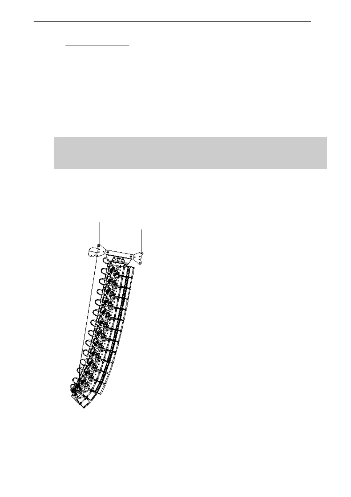
• Lower the array until the bottom cabinet is just
off the floor and the bumper is back to
horizontal.
• Rotate the LEVA1500 lever counterclockwise
until there is no tension on the GEO T kelping
chain and no compression on the system.
• Disconnect the LEVA1500 hook from the GEO
T bottom bumper and remove the bottom
bumper from the array. (You may have to
remove the T2815’s first)
• The array now hangs vertically.
• Link cables must be disconnected and stowed
away in the recesses in the rear of each
cabinet.
• NB : As the system is lowered it is good
practise to disconnect as many loudspeaker
cables as can be reached without climbing the
array. This ensures that a cable should not be
accidentally forgotten when the system is
separated. Damage to the connector will occur
should this mistake be made.
• In each group of 3 GEO T4805’s, the linking
bar of the lowest GEO T4805 should be
returned to the 5° position in order to sit flat in
the flight case.
•
10 GEO T 4805 + 2 GEO T 2815 SET IN COMPRESSION MODE
 Loading...
