NEXO NX242 DIGITAL CONTROLLER FOR GEO T Page 39/63
Other “loudspeaker management” DSP devices do not provide
the algorithms that the NX242 uses to optimise the cardioid
operation of the GEO T4805, CD18 and CD12.
GEO T4805 LF and CD18 dispersion are digitally set to a
cardioid pattern by adjusting the front and rear 8” loudspeakers
phase and amplitude relationship. Maximum attenuation is
achieved at 180°; average rear to front attenuation is more
than 12 dB.
GEO T2815 low frequency directional behaviour is achieved
by using rear radiating acoustic resistor. These are designed
so that LF dispersion is cardioid. Maximum attenuation is
achieved at 180°, average rear to front attenuation is more
than 12 dB.
4.3 GEO T NX242 Setups description
4.3.1 GEO T4805
Hardware configuration
• Input can be selected in the MENU 3.2 (L, R
or L+R)
• Output 1 drives the rear-firing LF 8 inch long
excursion neodymium cone transducers
• Output 2 drives the front-firing LF/MF 8 inch
long excursion neodymium cone transducers
• Output 3 drives the HF 3-inch voice coil, 1.4
inch exit neodymium compression driver
• Output 4 is not used.
Setups
Please refer to the latest version of the NX242 user manual
and firmware (www.NEXO-sa.com).
4.3.2 GEO T2815
Hardware configuration
• Input can be selected in the MENU 3.2 (L, R
or L+R)
• Output 1 is not used
• Output 2 drives the LF/MF 8 inch long
excursion neodymium cone transducers
• Output 3 drives the HF 3-inch voice coil, 1.4
inch exit neodymium compression driver
• Output 4 is not used.
INPUT R
INPUT L
OUTPUT CHANNEL 4
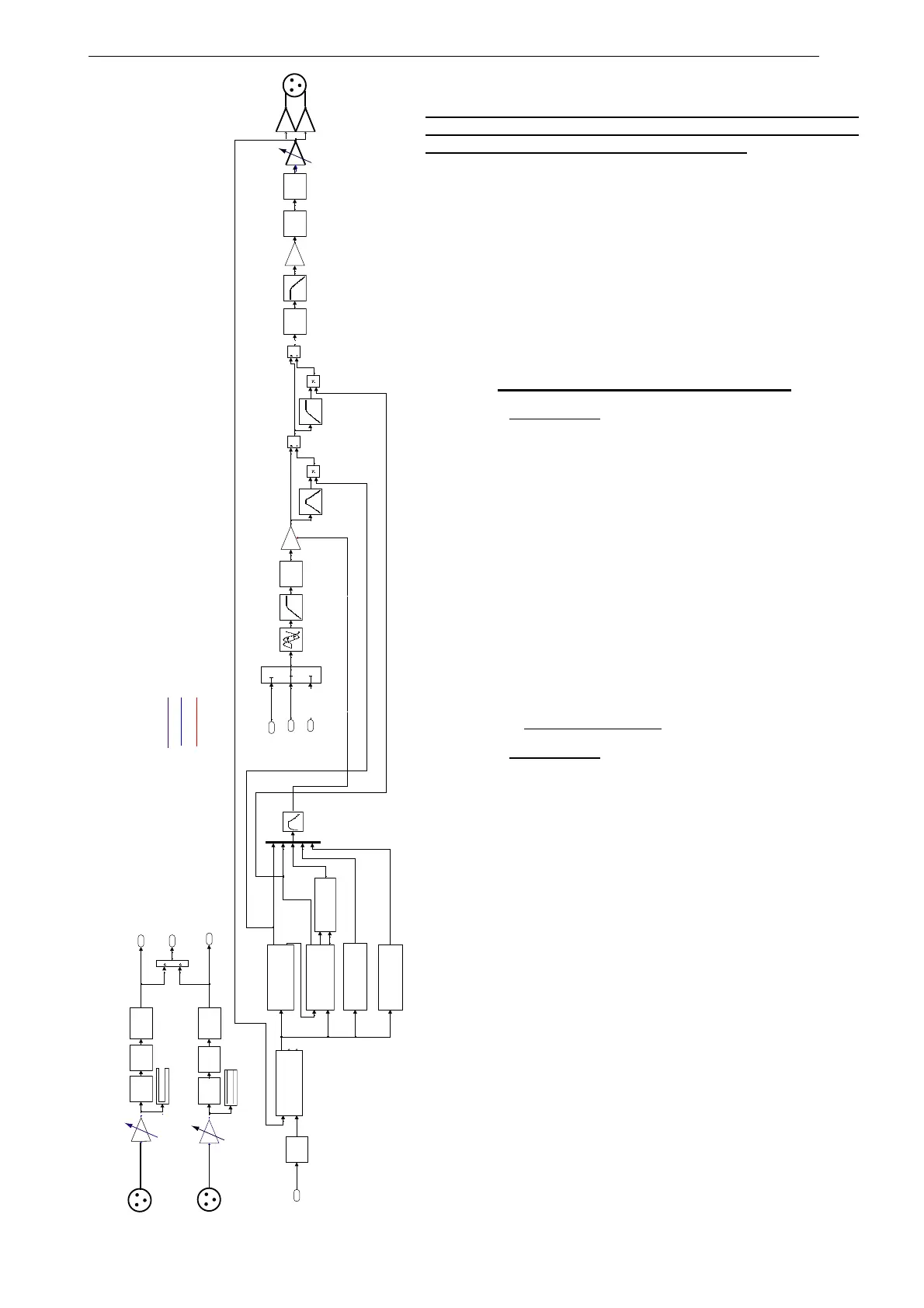
NX241 TDcontroller Partial BLOCK DIAGRAM
Analogue part
Digital Audio
Digital servo & protections
3
R+L
2
L
1
R
Voice Coil Temp.
ChassisTemp
Command
PHYSIO 1
Command
PEAK SIMULATION
PATCH
Disp.
Command
Voice Coil Temp.
ChassisTemp.
LF TEMPERATURE
INPUT VU-METER
INPUT VU-METER
AD EQ
AD
DACMUTEEQ
EQ
SHELVING
SHELVING
AD EQ
Command
HF TEMPERATURE
1
Gain2
VCA
FALLBACK
AMP VOLTAGE
Signal
AMP POWER
AMP GAIN
Command
displacement
DISPLACEMENT 1
DELAY 1
ATT/REL.
5
SENSE 1
3
L
2
R+L
1
R
 Loading...
