Page 6/63 GEO T GENERAL SET-UP INSTRUCTIONS
2 GEO T GENERAL SET-UP INSTRUCTIONS
2.1 Speaker Wiring
2.1.1 GEO T4805 & T2815 connectors
GEO T’s are connected to power amplifiers via one AP6 Male Connector (GEOT-612M) on a link cable
that is stowed in the rear vent port. One EP6 Female Chassis (GEOT-613F) on the back connector
panel is used as output to feed the next GEO T.
A wiring diagram is printed on the connection panel located on the back of each cabinet. The EP6 / AP6
connectors are linked in parallel within the enclosures (see the Connections Diagrams section of this
manual).
EP6/AP6 Pin # 1 / 2 3 / 4 5 / 6-
GEO T4805
Rear 8” LF - 32 Ω
1 Negative – 2 Positive
Front 8” LF/MF - 32 Ω
3 Negative – 4 Positive
1.4” HF – 16 Ω
5 Negative – 6 Positive
GEO T2815 Not connected
Through
Front 8” LF/MF – 32 Ω
3 Negative – 4 Positive
1.4” HF – 16 Ω
5 Negative – 6 Positive
IMPORTANT
NEVER USE a male connector to feed the signal:
High voltages and currents are delivered from the amplifiers to the GEO T system.
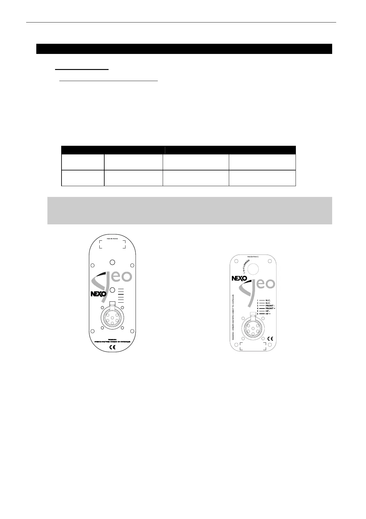
GEO T4805 REAR CONNECTOR PANEL GEO T2815 REAR CONNECTOR PANEL
1 BACK -
2
BACK +
3
FRONT -
4
FRONT +
5
HF -
6
HF +
 Loading...
