Doc# E107754 V.1.03 QS - 2
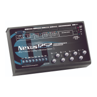
Nexus® 1252 Meter Quickstart
Electro Industries/GaugeTech
Mechanical Installation:
Mount the Nexus® 1252 Meter against any firm, flat surface. Use a #10 screw in each of the four slots on the
flange to ensure that the unit is installed securely. For safety reasons, mount the meter in an enclosed and pro-
tected environment, such as in a switchgear cabinet. Install a switch or circuit breaker nearby; label it clearly
as the meter’s disconnecting mechanism.
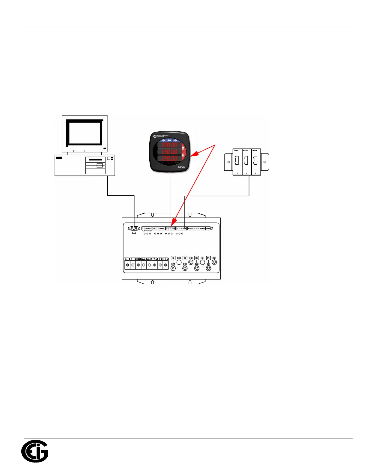
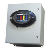
Installing an External Display:
The LED display P40N+ (shown above) mounts using a standard ANSI C39.1 drill plan.
1. Secure the four mounting studs to the back of the panel with the supplied nuts.
2. Insert one end of the supplied RS485 cable into Port 3 of the Nexus® meter (or to another Port set to a Baud
Rate of 9600 - see page QS-5 for instructions).
3. Insert the other end of the cable into the back of the Nexus® P40N+ Display.
NOTE: RS485 communication is viable for up to 4000 feet (1219 meters). If your cable length exceeds 200 feet
you must use a remote power supply, such as EIG’s PSIO.
Connect from one of the meter’s
RS485 ports to the RS485 connection
on the back of this display.
Nexus®1252 Meter
I/O
Modules
PC